


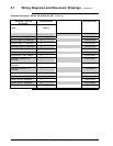

5.1 Wiring Diagrams and Dimension Drawings, Continued
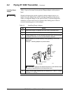
Dimension Drawings
The tables on the following pages list available dimension drawings for
reference. If you need a copy of a drawing, please determine the
appropriate drawing number from the following tables and contact your
Honeywell representative to obtain a copy.
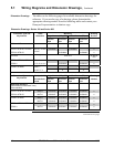
Dimension Drawings - Series 100 and Series 900
Transmitter Type and Table Mounting Drawing
Key Number Selections
Angle Bracket (MB), (SB) Flat Bracket (FB) Number
Vertical
Pipe
Horizontal
Pipe
Vertical
Pipe
Horizontal
Pipe
Differential Pressure
STD110, STD120, STD125*,
See Key Number
51205895 51205893
⇐
STD130, STD170
Column
51205894 51205892
⇐
*STD125 – Tank HTG 30756435-
000
STD904, STD924, STD930, Table I - 51500357 51500355
⇐
STD974 C, D, G, H, K, L 51500356 51500354
⇐
STD924, STD930 Table I - X X
A, B, E, F, J X X
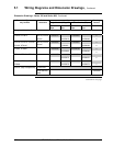
Transmitter Type and
Equipped with
Angle Bracket (MB), (SB) Flat Bracket (FB) Drawing
Key Number
A-G manifold
part #
Vertical
Pipe
Horizontal
Pipe
Vertical
Pipe
Horizontal
Pipe
Number
Differential Pressure
(with Anderson-Greenwood 3-way
valve manifold)
STD110, STD120, STD125*, M4AV1 51500426 51500424 51500428 51500422
⇐
STD130, STD170 M4TV1 51500427 51500425 51500429 51500423
⇐
STD924, STD930 M4AV1 51500431 51500433 51500435 51500437
⇐
M4TV1 51500430 51500432 51500434 51500436
⇐
STD904, STD924, STD930, M4AV1 51500442 51500440 51500444 51500438
⇐
STD974 M4TV1 51500443 51500441 51500445 51500439
⇐
Continued on next page
46 ST 3000 Release 300 Installation Guide 2/05