


2.3 Verifying Configuration Data, Continued
Procedure, continued
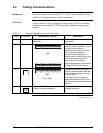
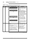
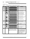
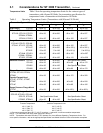
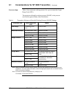
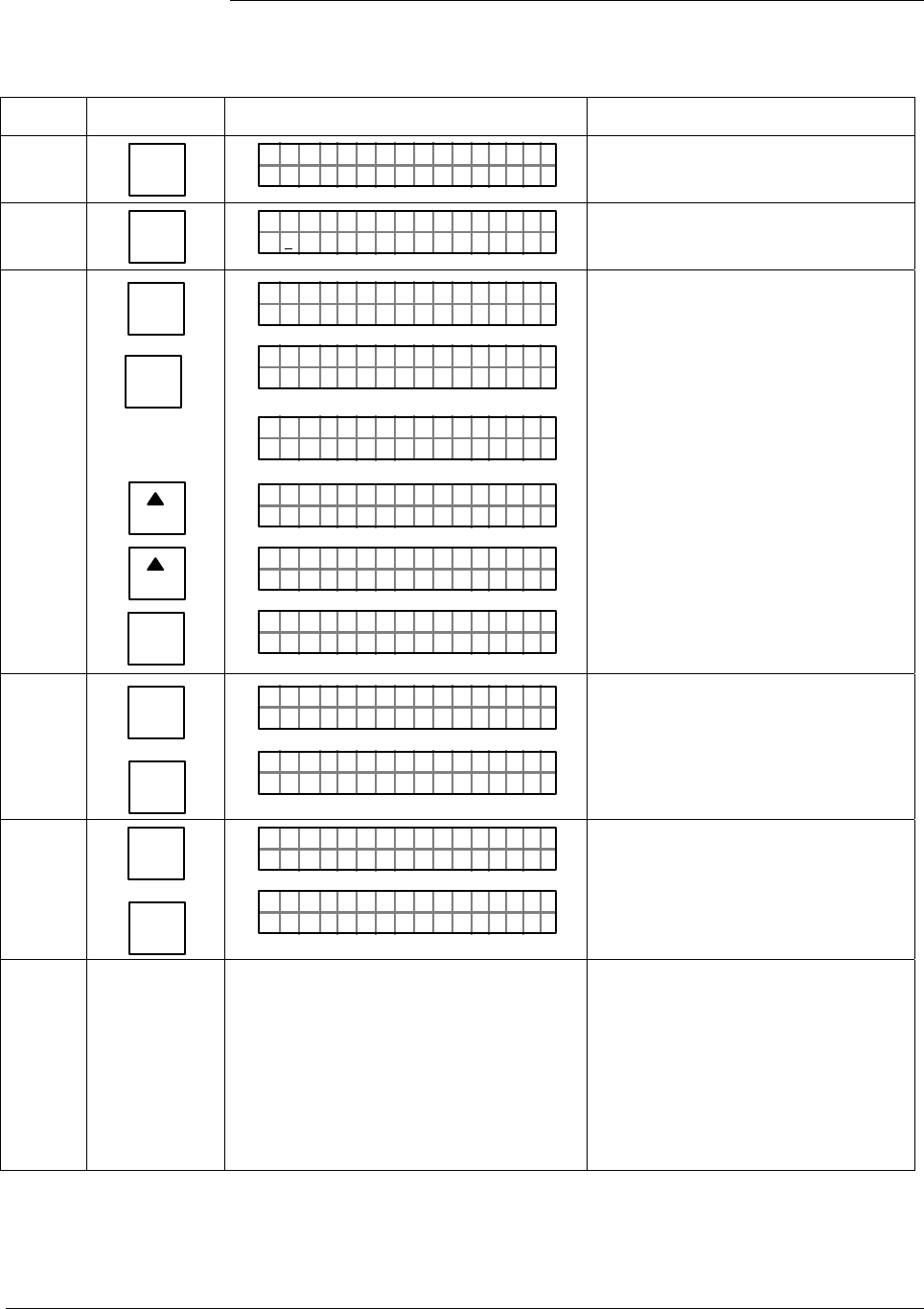
Table 3 Verifying Transmitter’s Configuration Data, Continued
Step Press Key Read Display or Action Description
5
E
LRV
0%
LRV 1
ØØØ
.
ØØ
"
H2O
_
39F
P T 1ØØ1S
Present Lower Range Value setting.
6
URV
100%
F
URV 1
3
.ØØ ØØ
"
H2O
_
39F
P T 1ØØ1S
Present Upper Range Value setting.
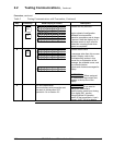
7
^
SHIFT
MENU
ITEM
DE CONF
I
NEXT
H
NEXT
H
CLR
(No)
FT–SH I
UR V 1 PT 1ØØ1S
DE OCNF
OR K NGCW .FSI
PT 1ØØ1S
..
eRgnliSn
DE OCNF
g
w/SV
PT 1ØØ1S
6B/Bw
DE OCNF
D
)(
yt
P T 1ØØ1S
e
/S=/
DE OCNF
BHiFO
PT 1ØØ1S
LIN DP
.Y. .RE AD
P T 1ØØ1S
Initiate shift key selection.
Access DE configuration menu.
These parameters apply for
transmitters in DE mode only.
Present output mode setting for
transmitter in DE mode.
Present broadcast format setting for
transmitter in DE mode.
Present failsafe mode setting for
transmitter in DE mode.
Exit DE configuration menu.
8
^
SHIFT
STAT
U
F/S DIR
LIN DP P T 1ØØ1S
FT–SHI
F/S I
/S FEFPSCAULE
DR
A
P T 1ØØ1S
Initiate shift key selection.
Default failsafe direction for analog
output. This applies for transmitter in
analog mode only.
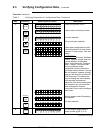
9
^
SHIFT
SPAN
Y
URL
FT–SHI
F/S ID R P T 1ØØ1S
URL 1
4.ØØ ØØ
"
H2O
_
39F
P T 1ØØ1S
Initiate shift key selection.
Factory set Upper Range Limit. This
can not be changed.
10
Turn off power and SFC. Remove power
leads and SFC leads from transmitter.
Replace integral meter, if applicable;
replace end-cap; and tighten end-cap
lock
This completes bench check unless
you want to change default failsafe
direction for analog output and/or
position of optional write protect
jumper. If you do want to change
failsafe direction or write protect
jumper, go to Section 2.4 or 2.5,
respectively. Otherwise, you can
now install transmitter.
12 ST 3000 Release 300 Installation Guide 2/05