


4.2 Piping ST 3000 Transmitter, Continued
Piping Arrangements,
continued
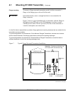
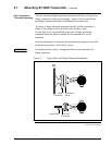
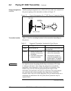
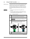
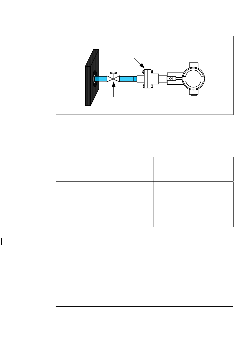
Another piping arrangement uses a block-off valve and a tee connector in
the process piping to the transmitter as shown in Figure 12.
Figure 12 Typical Arrangement for ½” NPT Process Connection Piping
Block-off Valve
1/2" NPT
Connection
Tank Wall
Transmitter location
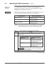
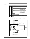
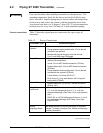
Table 11 lists the mounting location for the transmitter depending on
the process.
Table 11 Suggested Transmitter Location for Given Process
Process Suggested Location Explanation
Gases Above the gas line The condensate drains away from
the transmitter.
Liquids 1. Below but close to the
elevation of the process
connection.
2. Level with or above the
process connection.
1. This minimizes the static head
effect of the condensate.
2. This requires a siphon to
protect the transmitter from
process steam. The siphon
retains water as a “fill fluid.”
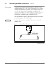
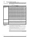
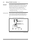
ATTENTION
For liquid or steam, the piping should slope a minimum of 25.4 mm
(1 inch) per 305 mm (1 foot). Slope the piping down towards the
transmitter if the transmitter is below the process connection so the
bubbles may rise back into the piping through the liquid. If the
transmitter is located above the process connection, the piping should
rise vertically above the transmitter; then slope down towards the
flowline with a vent valve at the high point. For gas measurement, use a
condensate leg and drain at the low point (freeze protection may be
required here).
Continued on next page
2/05 ST 3000 Release 300 Installation Guide
35