


Getting Started Connections Playback Remote Control Multi-Zone Information Troubleshooting Specifications
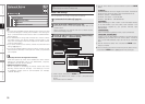
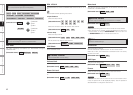
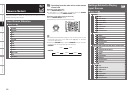
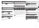
A4 Remote ID
Set remote control ID.
Match the ID setting of the remote control unit and the receiver.
• When changing the remote ID, also change the AMP, iPod, TU and
NET/DTU modes of the main remote control unit at the same time
(vpage 80).
• When changing the remote ID, also change the sub remote control
unit at the same time (vpage 85).
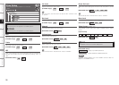
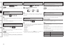
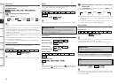
A3 Digital Out
Set usage of OPT4 OUT.
NOTE
The ZONE4 operations cannot be performed when set to “Rec
Select”.
[Selectable items]
ZONE4 Select
Rec Select
[Selectable items]
1
2
3
4
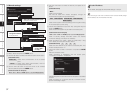
A5 2Way Remote
Set when using the 2-way remote control unit.
When using a 2-way remote control unit (RC-7000CI and RC-7001RCI,
sold separately), set this to “Used”.
[Selectable items]
Used
Not Used
NOTE
• When using the 2-way remote control unit, connect to the Port 1
RS-232C connector.
• If GUI menu “Manual Setup” – “Option Setup” – “2Way Remote”is
set to “Used”, you cannot use port 1 of the RS-232C terminal for the
external controller.
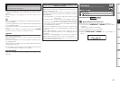
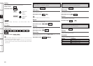
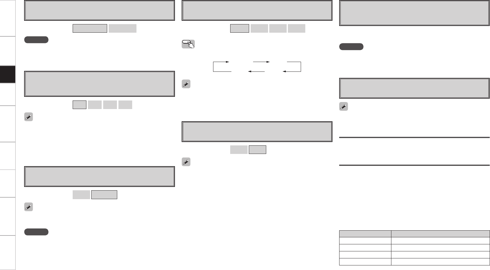
A6 Dimmer
Adjust display brightness of the receiver.
Operating from the main unit
Press the DIMMER button.
[Selectable items]
Bright
Dim
Dark
OFF
Bright Dim
DarkOFF
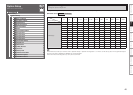
A7 Setup Lock
Protect settings from inadvertent change.
• When “Setup Lock” is set to “ON”, the settings listed below can
no longer be changed. Also, “SETUP LOCKED!” is displayed if you
attempt to operate related buttons.
⋅ GUI menu operations
⋅ RESTORER
⋅ Night Mode
⋅ Parameter
⋅ Room EQ
⋅ Channel Level
⋅ Audio Delay
• To cancel the setting, press the MENU button to re-display the
“Setup Lock” screen, then change the setting to “OFF”.
[Selectable items]
ON
OFF
A8 Maintenance Mode
This sets the function for maintenance by a DENON serviceperson
or installer. (For professional use only.)
NOTE
Only use this function if so instructed by a DENON serviceperson or
installer.
This function allows a DENON serviceperson or installer to check the
AVP-A1HDCI’s status and make settings via the Internet.
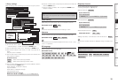
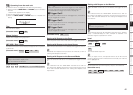
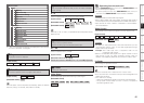
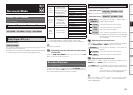
A9 Firmware Update
Update the firmware of the receiver.
Check for Update
You can check for firmware updates. You can also check approximately
how long it will take to complete an update.
Start
Execute the update process.
When updating starts, the power indicator becomes red and the GUI
screen is shut down.
The amount of update time which has elapsed is displayed during the
update process.
When updating is complete the power indicator becomes green and
normal status is resumed.
b
If the display reads as shown below, check the settings and network
environment, then update again.
Display Description
Updating failed Updating failed.
Login failed Failure to log into server.
Server is busy Server is busy. Wait a while then try again.
Connection fail Failure connecting to server.
If POA-A1HDCI is connected using the control link, POA-A1HDCI
meter operation is turned OFF when the AVP-A1HDCI display is
turned “OFF”.
If POA-A1HDCI is connected using the control link, POA-A1HDCI is
updated simultaneously with update of AVP-A1HDCI.
Setup