


Getting Started Setup Playback Remote Control Multi-Zone Information Troubleshooting Specifications
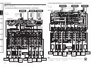
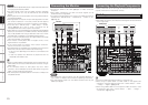
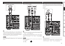
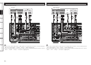
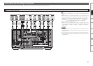
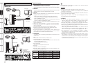
Carefully check the left (L) and right (R) channels and the inputs and outputs, and be sure to interconnect correctly.
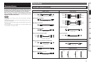
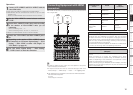
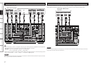
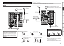
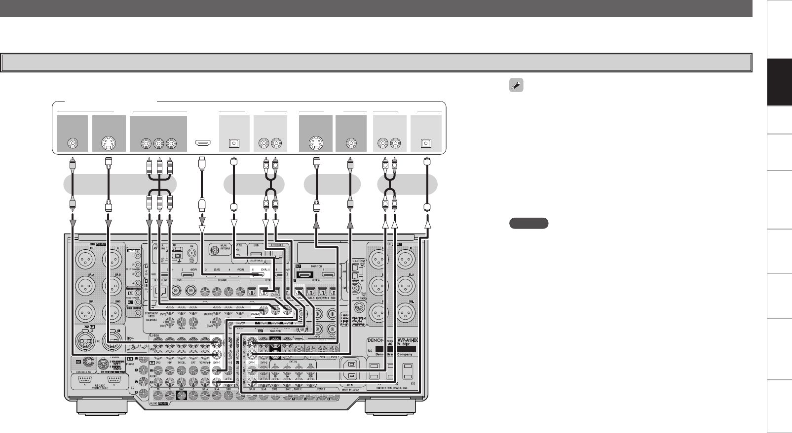
Connecting the Recording Components
Digital Video Recorder
Connect the cables to be used.
R
L
R
L
R
L
R
L
47*%&0 47*%&0
*/
3-3-
*/
*/
"6%*0 "6%*07*%&0 7*%&0
*/065
015*$"- 015*$"-
065
"6%*0 "6%*0
065
7*%&0 7*%&0
065
065
)%.*
$0.10/&/57*%&0
: 1# 13
065
Digital video recorder
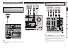
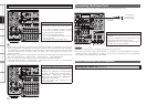
NOTE
• Do not connect the output of the component connected to the AVP-
A1HDCI’s OPTICAL2 output connector to any input connector other
than OPTICAL2.
• Do not connect the output of the component connected to the AVP-
A1HDCI’s OPTICAL3 output connector to any input connector other
than OPTICAL3.
• Make analog connections if you wish to record analog audio
signals.
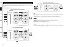
• When recording to a digital video recorder, it is necessary that the
type of cable used with the playback source equipment be the same
type that is connected to the AVP-A1HDCI DVR-1 OUT connector.
Example: TV IN → S-Video cable : DVR-1 OUT → S-Video cable
TV IN → Video cable : DVR-1 OUT → Video cable
• Connect a DVR-2 in the same way.
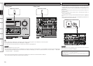
• When using a component video cable or a BNC cable for the
component video connection make the settings at GUI menu
“Source Select” – “DVR-1” or “DVR-2” – “Assign” – “Component”
(vpage 48).
Connections