ENGLISH
10
L
R
AUDIO
OUT
L
R
LR
OUT IN
L
R
AUDIO
OUT
OPTICAL
B
R
L
L
R
L
R
L
R
L
R
R
L
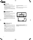
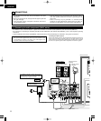
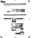
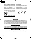
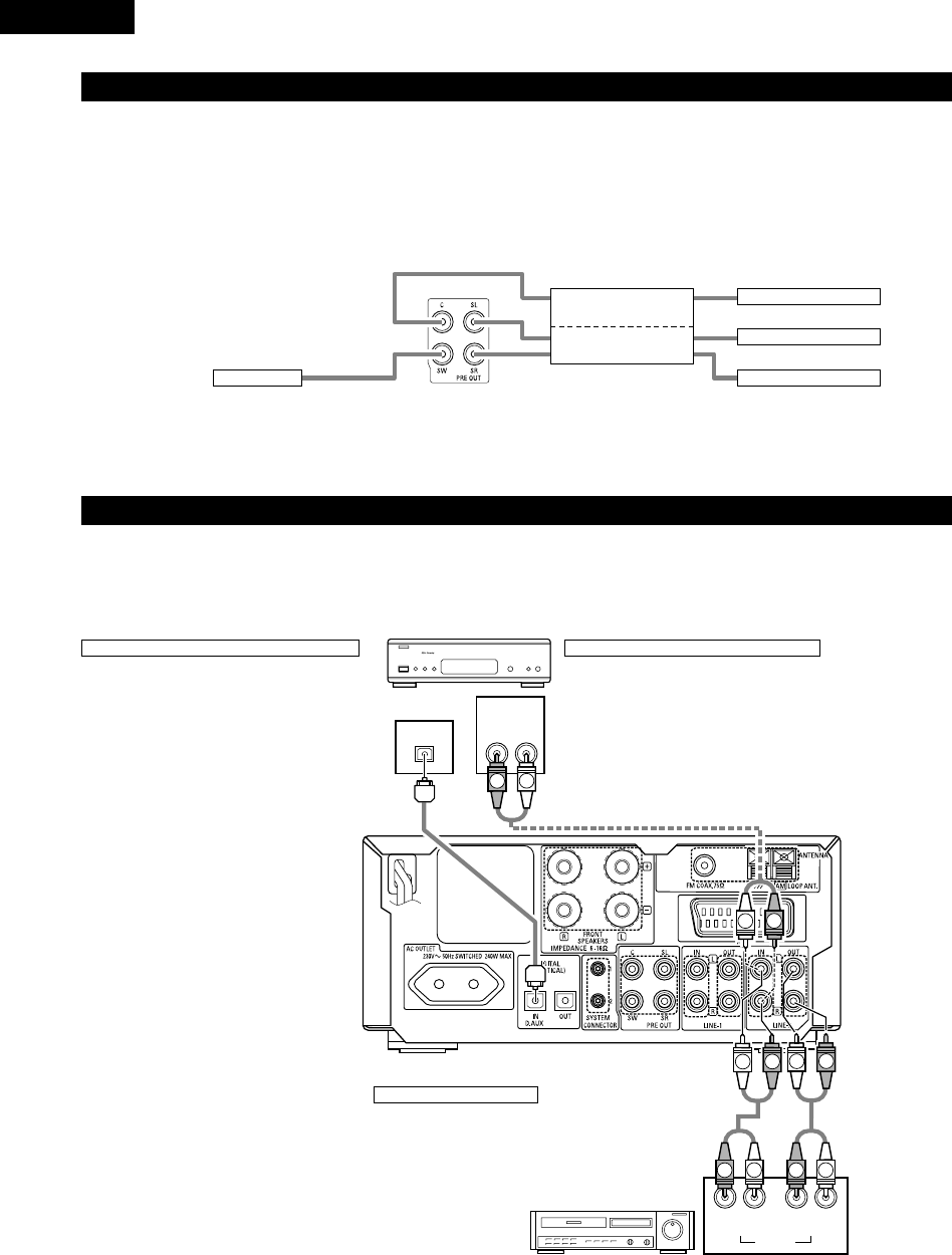
(3) Connecting the Audio Signals of a Digital Satellite Tuner and VCR
• Connect the video signals directly to the TV and switch the picture on the TV.
• When making connections, also refer to the operating instructions of the other components.
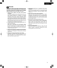
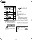
Connection to the optical digital input terminal
• Only audio signals are input to the optical digital
input terminal.
• Use a commercially available optical transmission
cable for connection to the optical transmission
terminal (OPTICAL).
Connection of a digital satellite/cable tuner
• For tuners equipped with an optical digital output terminal,
connect the digital output terminal to the DIGITAL D.AUX IN
terminal on the ADV-M71 using an optical transmission cable.
• To connect the audio output terminals, use whatever of the
ADV-M71’s LINE-1 or LINE-2 terminals are open.
Connection of a video deck
• Connect the video deck’s audio output and audio input
terminals to whatever of the ADV-M71’s LINE-1 or LINE-2
terminals are open using pin-plug cords.
Video deck
Digital satellite/cable tuner
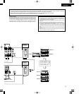
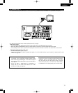
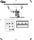
(2) Connecting the PRE OUT terminals (only with multi-channel settings)
• When used in combination with a commercially available subwoofer with built-in amplifier and power amplifier, the ADV-M71 can be expanded
into a 5.1-channel surround system.
• When making connections, also refer to the operating instructions of the other components.
• To make the 5.1-channel setting, set the speakers to “5.1 CH SURROUND” in the quick system setup and select “Room Setting” and
“Listening Position”. (See pages 31 to 32.)
SUBWOOFER
• Connect the subwoofer with built-in
amplifier.
POWER AMPLIFIER
(for center ch)
POWER AMPLIFIER
(for Surround ch)
• Connect the power
amplifier for center and
surround speaker
system.
Center Speaker
Surround (L) Speaker
Surround (R) Speaker
IN
IN
IN
IN


