


Drive System
Voltage and
Current Checks
Step 1
Step 2
Step 3
Step 4
77
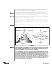
• Check security of antenna mounting and interconnecting assembly hardware. Be cer-
tain all electrical grounding connections (including cross-axis grounding straps) and
intact and secure, not corroded or broken. Thoroughly clean any noticeable corroded
portions of grounding cables, unplated portion of universal terminals and corresponding
mounting surfaces with a wire brush. Replace rather than tighten any loose A-325 struc-
tural hardware. The hardware distorts at initial installation and once loosened will not
maintain the required high strength friction connection. All other assembly and installa-
tion hardware should be tightened to its original torqued condition. When installing new
structural hardware, do not use a wrench with a lever arm longer than two feet.
• Examine painted aluminum and galvanized surfaces and touch-up where required.
At the conclusion of the installation procedure and prior to turning the system over to the
station facility, an installation acceptance check-off sheet was prepared and duly signed
off if installed by an Andrew crew. Part of this check-off included voltage readings retak-
en to determine if proper voltage was available. Current readings were also taken as a
reference for future comparison to serve as a troubleshooting aid in determining possi-
ble equipment degradation and shortened life. Any current reading taken during the fol-
lowing procedure that significantly varies by more than five percent from the preestab-
lished reference values necessitates trouble shooting the particular system involved to
determine the cause and required corrective action.
Approximately every three months and during a period of down time, disconnect as
applicable the RF transmitter and all power supplies. The main disconnect switch in the
main load center box at the antenna site must be in the ON position and the detachable
hand-held controller assembly must be plugged in.
Open the outer local control/motor drive controller door at the antenna site to gain
access to the conductors supplying power to the azimuth, elevation and polarization
drive motors. Turn the primary power disconnect switch to the ON position.
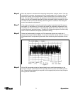
Turn the Az/El speed switch to the FAST position. Turn the AZIMUTH EAST/WEST
switch to either position and while the antenna is rotating, carefully use a clamp-on
ammeter in accordance with the ammeter manufacturer’s instructions to take current
readings off each of the power conductors (phases) connected to the main terminal
block at the bottom of the panel. Record the current draw in the equipment log and com-
pare the readings to the reference values entered in the installation/acceptance check-
off. If the readings differ significantly, refer to the appropriate troubleshooting information
and perform the applicable corrective action. Then take voltage readings off each of the
three conductors; the readings should agree with each other - within two percent. Turn
the AZIMUTH switch to OFF.
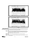
Repeat preceding step (3) with the AZIMUTH EAST/WEST switch in the alternate oper-
ating position.
Preventive Maintenance