


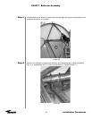
Step 12
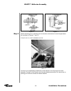
Step 13
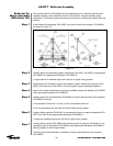
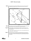
Step 14
62
Installation Procedures
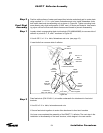
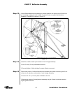
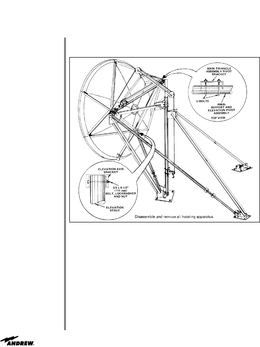
Hoist reflector/backstructure assembly to vertical position until upper joints of main trian-
gle assembly contact pipe and straddle two locator bars on support and elevation
assembly (P/N 49635) as shown in Figure 75.
Figure 75
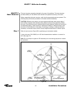
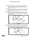
Install two U-bolts at each pivot bracket of main triangle assembly.
• Use 1/2 inch (13 mm) lockwashers and nuts.
• Securely tighten U-bolts allowing for some reflector movement
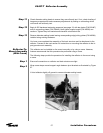
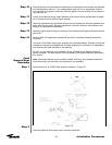
Raise lower portion of reflector/backstructure assembly and attach remaining end of ele-
vation strut to elevation axis bracket of main triangle assembly.
• Use 3/4 x 4-1/2 in (114 mm) bolt, lockwasher and nut
• Mechanical means or fine adjustment assembly may be utilized to achieve elevation
angles greater than 300.
ES45T-T Reflector Assembly