


Step 8
Step 9
Step 10
Step 11
61
Installation Procedures
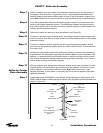
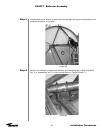
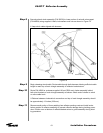
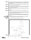
Securely attach winch assembly (P/N 39532) to lower portion of azimuth axis support
(P/N 49634) using supplied U-bolts, lockwashers and nuts as shown in Figure 74.
• Keep winch cable aligned with sheaves
Figure 74
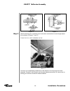
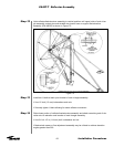
Begin releasing winch cable. Route cable through both sheaves allowing sufficient cable
length to reach top of main triangle assembly on reflector backstructure.
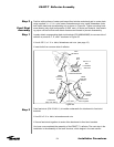
Route P/N 43909 or customer-supplied 18-foot (5500 mm) choker assembly behind
both pivot brackets of main triangle assembly as shown. Attach end of choker to winch
or crane cable hook.
• Distance between choker/winch connection and top of main triangle assembly should
be approximately 13 inches (330 mm).
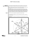
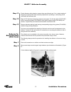
Remove small portion of foam padding from reflector packing crate and install under
bottom portion of reflector assembly to prevent reflector damage during hoisting proce-
dure. Position man at bottom of reflector/backstructure to guide assembly during hoist-
ing procedure.
ES45T-T Reflector Assembly