


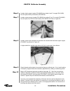
Step 6
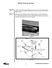
Step 7
Step 8
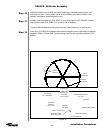
Step 9
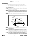
Step 10
35
Installation Procedures
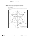
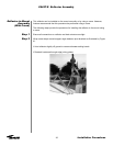
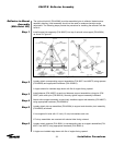
Loosely attach support angles (P/N 49438) from plates A and C to angle (P/N 49436)
from tee plate B with pivot bracket (P/N 300745).
Loosely connect support angles (P/N 49438) from plates E and C to angle (P/N 49436)
from tee plate D to elevation axis bracket (P/N 300749) as shown in Figure 39.
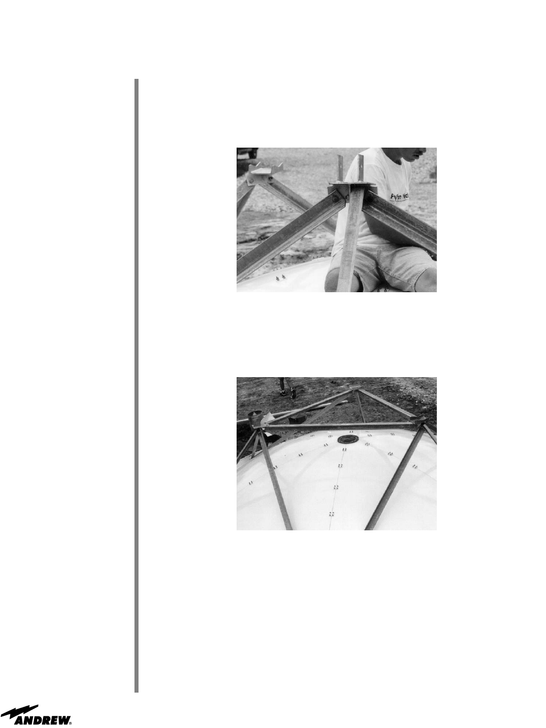
Figure 39
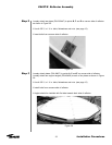
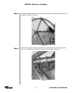
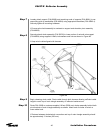
Loosely connect pivot brackets and elevation axis bracket with the three support angles
(P/N 49437) as pictured in Figure 40.
• Angles should be installed edge down with flat of angle away from reflector.
Figure 40
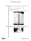
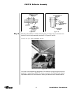
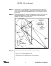
Check diameter setting bands to ensure that they are uniformly taut. If not, check leveling
of temporary supports and make necessary adjustments by adding or subtracting shims.
Begin A-325 hardware tensioning procedure (see page 12) . Work from connections
closest to backside of reflector to those connections furthest away in this order: Start
with plates (P/N 49427) and tee plates (P/N 202447). Next tighten support angle con-
nections. Tighten the pivot brackets and elevation axis bracket last.
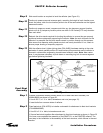
You have now completed the assembly of the back structure and its attachment to the
reflector. Proceed to the next section for instructions on mounting the reflector to the tri-
pod ground mount assembly with a crane, or the appropriate section for instructions on
mounting the reflector with the hoist kit.
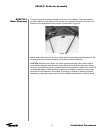
ES45T-R Reflector Assembly