


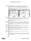
Step 2
Step 3
Step 4
Step 5
Step 6
52
Installation Procedures
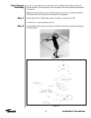
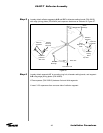
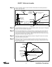
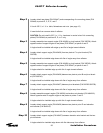
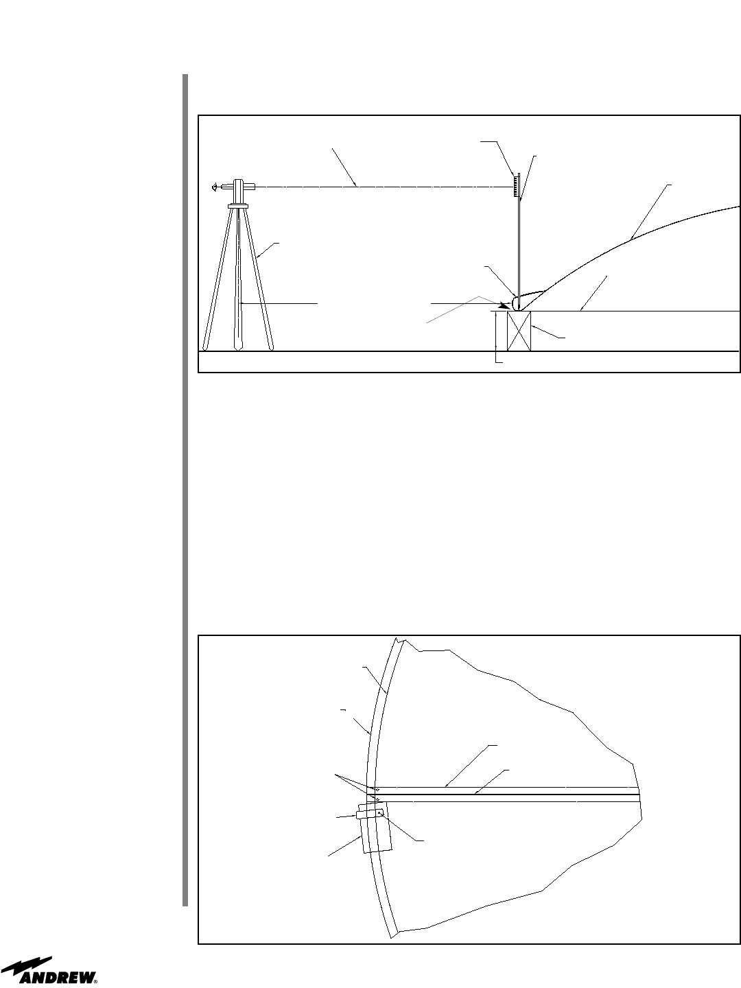
Position theodolite, transit or laser level about 10 feet [3m] from outside perimeter of
reflector (see Figure 62).
Figure 62
Line of Sight
(0.0° Elevation)
Steel Rule
0.03-0.06 Inch
Increment
(0.5-1.0 mm)
Pointed Measuring Rod
6’ (1.8 m)
Reflector
Diameter Setting Band
Temporary Support
12 Inch (300 mm)
Shim Stack - Not
Shown for Clarity
Approx. 10 Feet (3 m)
Theodolite,
Transit or
Laser Level
Reflector
Turn Back
Level theodolite/transit/laser level. If using theodolite, position view scope at 0.0 degrees
elevation, lock down elevation adjustment.
Site through theodolite/transit to determine where on measuring rod to place steel rule
onto rod to allow visibility of steel rule through theodolite/transit/laser level at all (6) six
measurement locations around reflector. Securely fasten both ends of steel rule to mea-
suring rod with adhesive tape (see Figure 62).
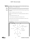
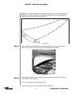
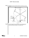
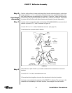
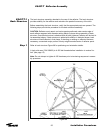
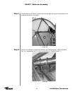
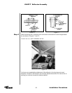
Temporary supports should be positioned as shown in Figure 63, close to but not inter-
fering with diameter setting bands.
Referring to Figure 63, mark the measuring location at each of the six temporary sup-
port locations with a small dot (use felt tip marker) to be used as reference point in sub-
sequent measurements.
Reflector
Turnback
Outside Edge
of Reflector
Setting Band
Hardware (2)
Shim Stack
(as required)
Temporary
Support
Measurement Location
Directly Above Shim Stack
Diameter Setting
Band (Hidden)
Reflector Seam
Seam Hardware Not Shown for Clarity
Figure 63
ES45T-T Reflector Assembly