Step 8
Step 9
Step 10
Step 11
Step 12
Step 13
Step 14
44
Installation Procedures
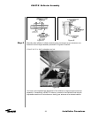
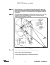
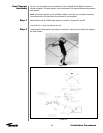
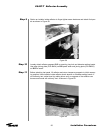
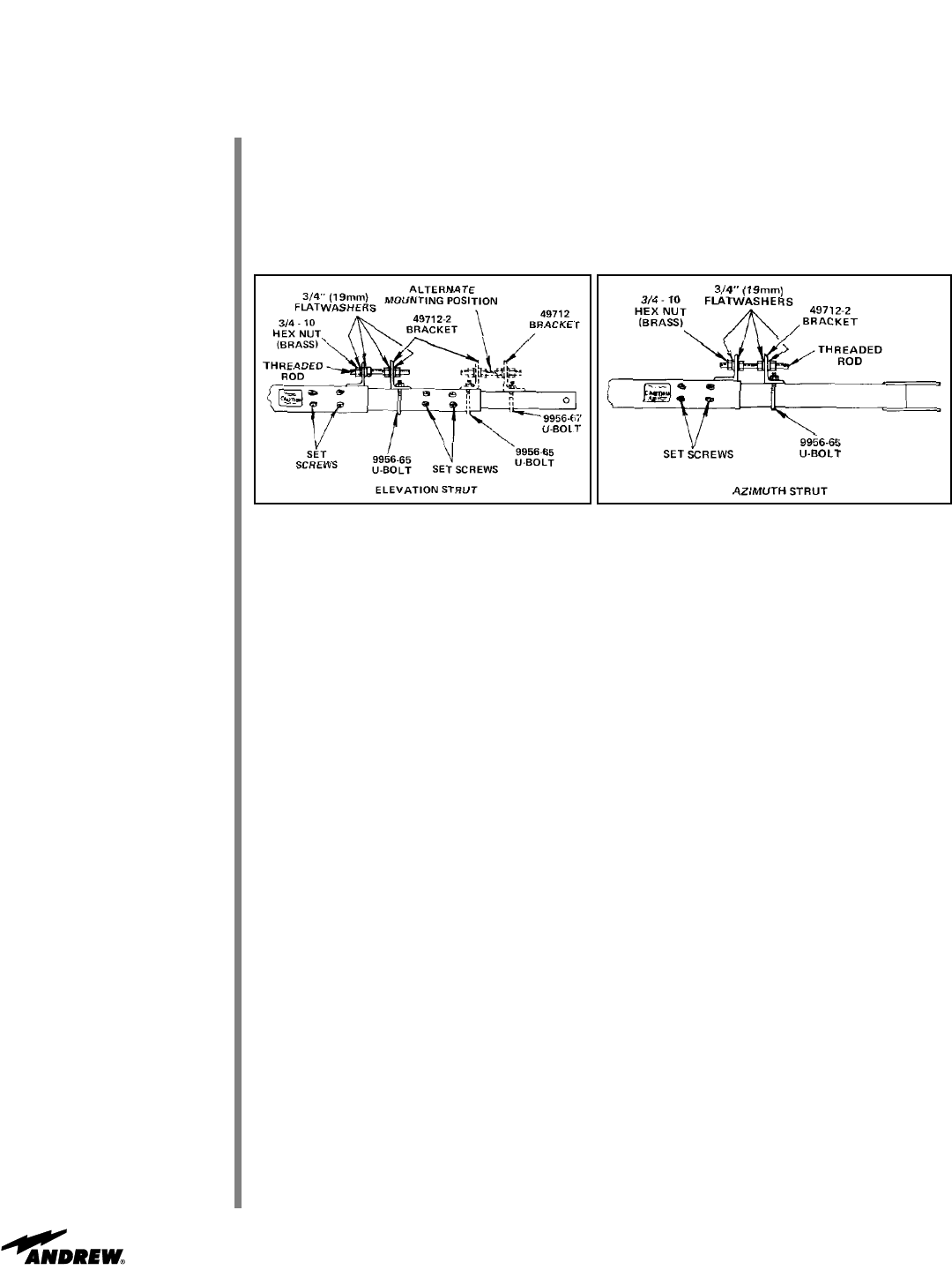
Attach fine adjustment assembly between adjacent azimuth strut sections as shown in
Figure 51 using appropriate brackets, U-bolts, brass hex nuts, flatwashers and threaded
rod. Securely tighten all adjustment assembly hardware.
Note: Fine adjustment assembly on azimuth strut should be positioned away from
ground mount angles.
Set fine elevation and azimuth strut positions by loosening strut set screws and selected
out fine adjustment hex nut. Turn corresponding inner hex nut in appropriate direction
until required strut length is achieved. Securely tighten strut set screws and correspond-
ing outer hex nut.
During final electrical tuning, adjust elevation and azimuth struts appropriately to length-
en or shorten struts for optimal signal strength.
After fine adjustments are complete, ensure strut set screws are securely tightened to
50-60 ft-lbs and spray with zinc-rich paint. Securely tighten hex nuts and U-bolts on
both elevation and azimuth fine adjustment assemblies.
Securely tighten eight U-bolts on elevation pivot assembly and upper and lower azimuth
axis joints.
Remove both fine adjustment assemblies and store in weather protected location for
future use.
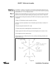
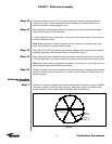
You have now finished aiming your antenna at the desired satellite. Proceed to the feed
support installation section for instructions on assembling and attaching the feed support
assembly to the reflector.
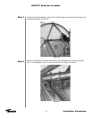
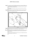
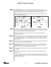
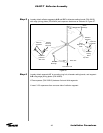
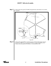
Fine Adjustment. Attach fine adjustment assembly between adjacent elevation strut
sections as shown in Figure 50 using appropriate brackets, U-bolts, brass hex nuts, flat-
washers and threaded rod. Securely tighten all adjustment assembly hardware.
Note: Adjustment assembly may also be attached in alternate position shown depend-
ing on required elevation angle.
Figure 50
Figure 51
ES45T-R Reflector Assembly


