


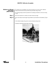
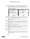

Step 7
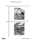
Step 8
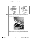
Step 9
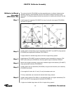
Step 10
40
Installation Procedures
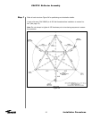
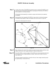
Loosely attach support (P/N 49060) and remaining ends of supports (P/N 49061) to cor-
responding pick-up assemblies (P/N 49064) using appropriate hardware (P/N 45980-1).
Securely tighten all mounting hardware.
• Ensure entire hoist assembly is centered on support and elevation pivot assembly
(P/N 49635)
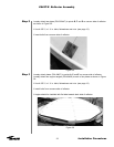
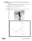
Securely attach winch assembly (P/N 39532) to lower portion of azimuth axis support
(P/N 49634) using supplied U-bolts, lockwashers and nuts as shown in Figure 48.
• Keep winch cable aligned with sheaves
Figure 48
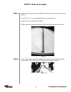
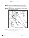
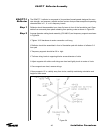
Begin releasing winch cable. Route cable through both sheaves allowing sufficient cable
length to reach top of main triangle assembly on reflector backstructure.
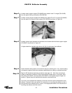
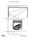
Route P/N 43909 or customer-supplied 18-foot (5500 mm) choker assembly behind both
pivot brackets of main triangle assembly as shown. Attach end of choker to winch or
crane cable hook.
•
Distance between choker/winch connection and top of main triangle assembly should
be approximately 13 inches (330 mm).
ES45T-R Reflector Assembly