


29
Installation Procedures
Reflector Leveling
Procedure
Step 1
Step 2
Step 3
Step 4
Step 5
Step 6
Step 7
Step 8
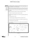
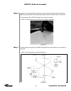
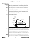
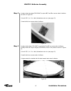
Position (6) temporary supports near panel seams exactly as shown in Figure 29.
Note: Temporary supports should be large enough to adequately support the reflector
and strong enough to easily support reflector weight without compressing.
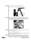
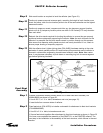
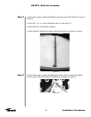
Position theodolite, transit or laser level about 10 feet [3m] from outside perimeter of
reflector (see Figure 30).
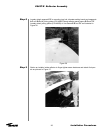
Level theodolite/transit/laser level. If using theodolite, position view scope at 0.0 degrees
elevation, lock down elevation adjustment.
Site through theodolite/transit/laser level to determine where on measuring rod to place
steel rule onto rod to allow visibility of steel rule through theodolite/transit at all (6) six
measurement locations around reflector. Securely fasten both ends of steel rule to mea-
suring rod with adhesive tape (see Figure 30).
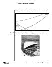
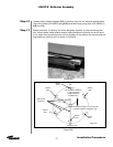
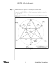
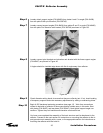
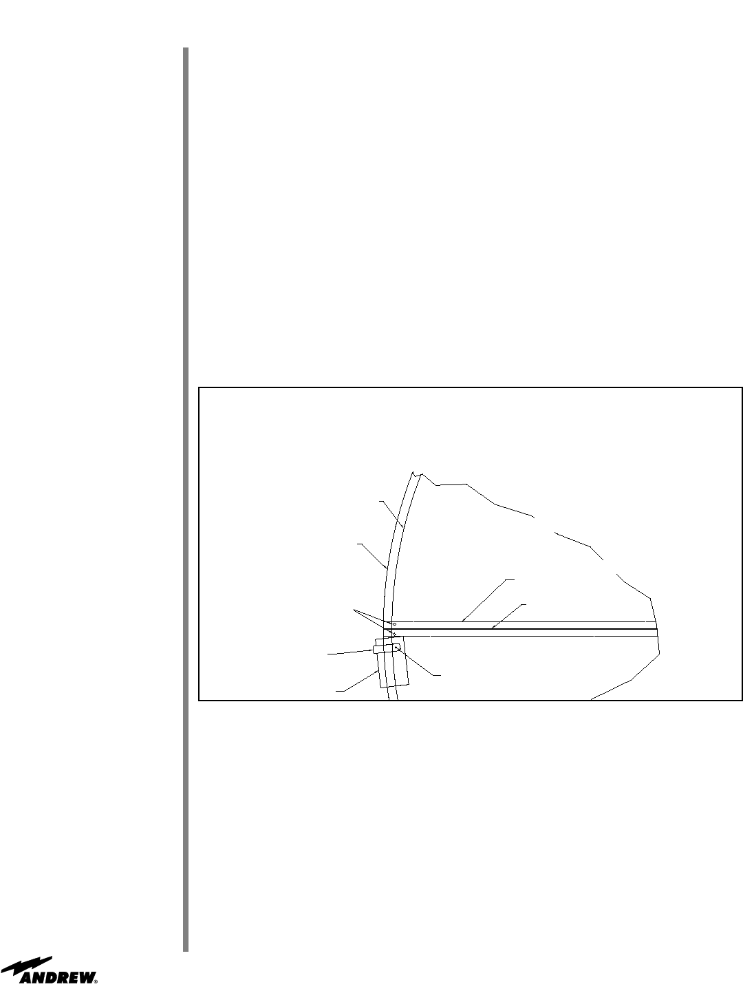
Temporary supports should be positioned as shown in Figure 31, close to but not inter-
fering with diameter setting bands.
Referring to Figure 31, mark the measuring location at each of the six temporary sup-
port locations with a small dot (use felt tip marker) to be used as reference point in sub-
sequent measurements.
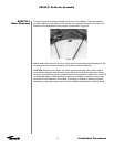
Position measuring rod point down over temporary supports and on the flat portion of
the aperture face as shown in Figures 30 and 31, using theodolite/transit/laser level
carefully measure and record relative height of each of the (6) temporary support loca-
tions. Note: Measuring rod must be held in a vertical position during all measurements.
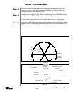
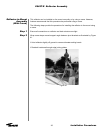
From the recorded data determine the relative height of each of the locations as com-
pared to the highest measured location. The differences between the highest location
and a lower location will be the amount of shim material required to place between the
reflector and the temporary support.
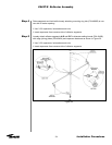
Reflector
Turnback
Outside Edge
of Reflector
Setting Band
Hardware (2)
Shim Stack
(as required)
Temporary
Support
Measurement Location
Directly Above Shim Stack
Diameter Setting
Band (Hidden)
Reflector Seam
Seam Hardware Not Shown for Clarity
ES45T-R Reflector Assembly
Figure 31