


Step 9
Step 10
Step 11
Step 12
Step 13
Feed Strut
Assembly
Step 1
Step 2
30
Installation Procedures
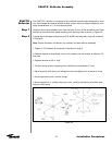
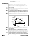
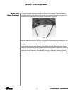
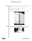
Shim each location as required to level the reflector (see Figure 31).
Continue to measure around antenna again, recording the height of each location mea-
sured. As before, shim the low location points to be at the same elevation as the highest
measured location.
Continue to measure, record, compare and shim any low temporary support location
points until all (6) temporary location points are within 0.030 inches [0.75 mm] elevation
from each other.
Recheck the shim stacks required for leveling the reflector to ensure they are properly
positioned and are adequately supporting the reflector. Note: As work continues on the
reflector it is essential that the shim stacks remain in position through out this process.
Also ensure that diameter setting bands are taut and evenly tensioned. If not, check to
ensure proper leveling of temporary supports.
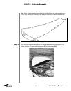
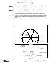
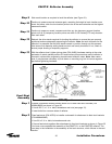
With the reflector level, tighten joining plate (P/N 49425) hardware starting at the outer
perimeter of match marked position A-A and continue this procedure around reflector in
concentric circles while progressing inward toward reflector vertex. Note: Near vertex
area, it may become necessary to push down on mounting ring hub to narrow segment
gap before tightening hardware.
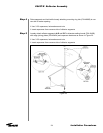
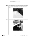
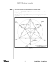
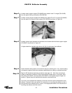
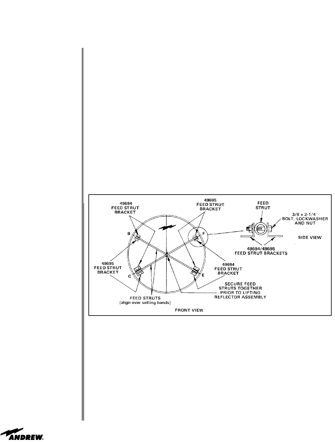
Installer underneath reflector should attach four of each feed strut brackets (P/N
49694/49695) as shown in Figure 32.
•
Use A-325 ½ x 1-¼ in. bolts, flatwashers and nuts (see page 12).
• Insert bolts from concave sides of reflector
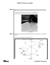
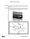
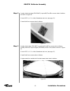
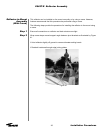
Pass feed struts (P/N 49703) to installer underneath for attachment to feed strut brackets
(P/N 49694/49695).
• Use 3/8 x 2-¼ in. bolts, lockwashers and nuts
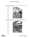
• Secure feed struts together after attachment to feed strut brackets as shown in Figure 32
You have now completed the assembly of the ES45T-R-1 or the ES45TDR reflector. The
next step in the installation is the assembly of the back structure, which follows in the next
section.
ES45T-R Reflector Assembly
Figure 32