


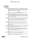
Step 12
Step 13
Step 14
Step 15
Step 16
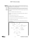
Reflector Leveling
Procedure
Step 1
51
Installation Procedures
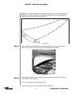
Install final reflector panel (C-D) by loosely attaching to diameter setting bands and
mounting ring hub. Loosely attach panel seam hardware as installer inside moves
reflector segment to enable segment union.
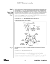
Begin attaching corresponding reflector rib segments at match-marked position A-A
using reflector segment seam hardware.
•
Insert capscrews from concave side - firmly push bolts through holes until bolt head is
flush with reflector surface
Note: Slight pressure on reflector segment may be necessary to enable proper align-
ment. Do not attempt to thread bolts into holes
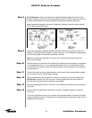
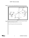
Insert shim (P/N 200215) between each reflector segment around perimeter of reflector
assembly beginning with seam A-A. Refer to Figure 28B, Page 27.
Begin tightening seam hardware at outer perimeter of reflector starting with seam A-A.
Continue tightening in concentric circles from reflector rim toward the mounting ring hub.
Note: Near center area it may become necessary to push down on mounting ring hub to
narrow segment gap before tightening hardware.
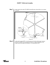
Tighten mounting ring hub and diameter setting band hardware. Diameter setting bands
should be uniformly taut at this point. If not, add or subtract shims to ensure proper lev-
eling of supports.
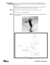
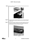
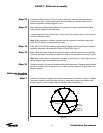
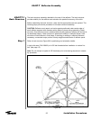
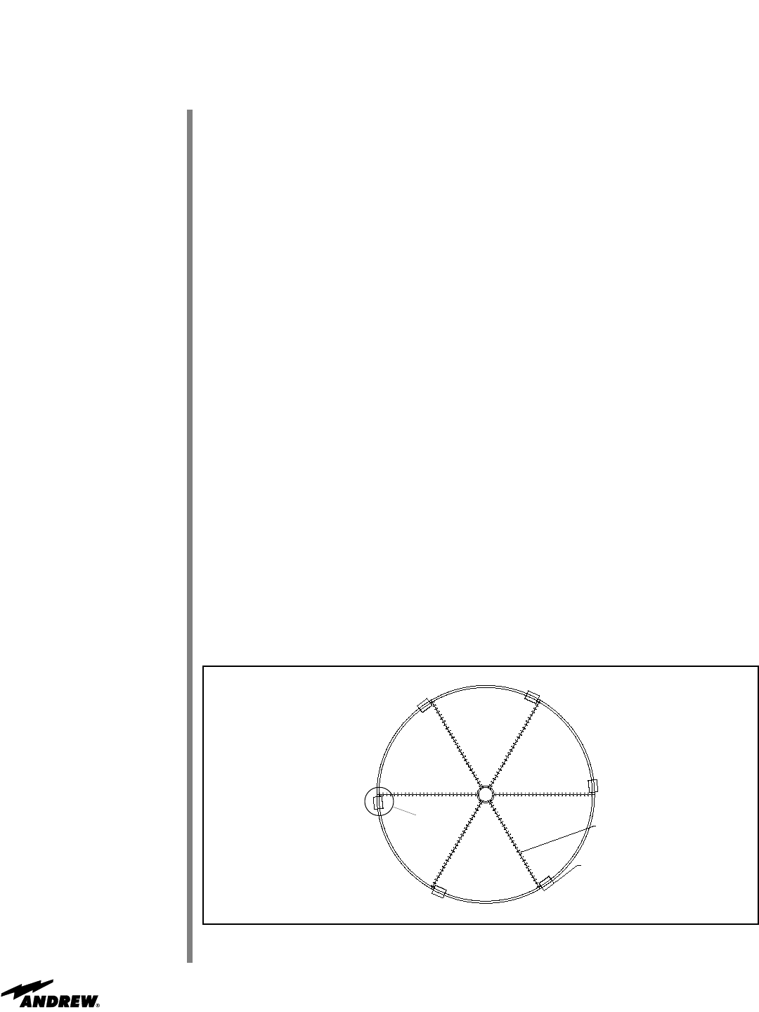
Position (6) temporary supports near panel seams exactly as shown in Figure 61. Note:
Temporary supports should be large enough to adequately support the reflector and
strong enough to easily support reflector weight without compressing.
Figure 61
Panel
Seams (6)
Temporary
Supports (6)
Refer to
Figure 7
ES45T-T Reflector Assembly