


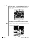
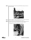
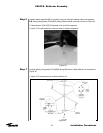

Step 16
Step 17
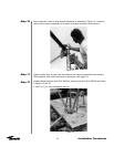
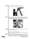
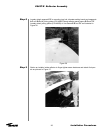
Step 18
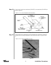
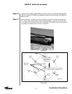
Step 19
21
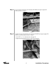
Connect U-bracket (P/N 49704) to appropriate connection plate.
• Use A-325 ½ x 1-½ in. bolts, flatwashers and nuts. (see page 12)
Installation Procedures
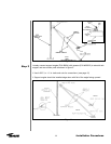
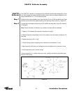
Figure 18
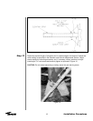
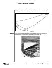
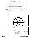
Determine required length of azimuth strut to nearest degree increment of desired
azimuth setting as specified in the Elevation and Azimuth Adjustments Section. Adjust
azimuth setting by withdrawing secondary strut to achieve necessary length. Install four
½ in. set screws and securely tighten as demonstrated in Figure 19.
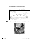
Figure 19
Connect one end of azimuth strut (P/N 49767) to connection plate with U-bracket (P/N
49704) as indicated in Figure 18.
• Use ¾ x 4-½ in. bolts, lockwashers and nuts
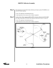
Securely tighten all A-325 ground mount hardware except the fine adjustment hardware
per A-325 tensioning procedure (see page 12).
The tripod ground mount assembly is now completed with the necessary operational
essentials. All ground mount options have separate instructional bulletins located in the
parts kit that contain the option.The next step in the installation process is the reflector
assembly. Proceed to the appropriate section for the type of reflector you are installing.