


Model MRC88 Page: 59
© 2003 Xantech Corporation
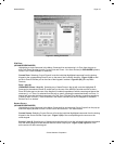
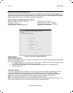
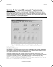
6. Select POWER OFF in the Macro Command List. The POWER OFF button will become outlined in
RED.
7. Select the appropriate command(s) to be associated with the absence of a Sense Input (i.e. no video or
0VDC on the Ring of the stereo mini jack connected to the SENSE input).
8. Repeat for all trigger inputs desired
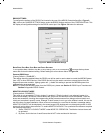
P
OLARITY AND WIRING OF SENSE INPUT
TIP = +12VDC Output
RING = Input (+12VDC)
SLEEVE = Ground
When using a dry contact closure to activate a Current Sense Input Trigger, the switch should be connected
between TIP and RING through a 220ohm resistor.
When using an external trigger voltage, (12 VDC control out from switched source, etc.) the switch should be
between SLEEVE and RING.
C
URRENT SENSE DE-BOUNCE SETTINGS
“De-Bounce” is the amount of time switches and relays need to stabilize. The factory default of ‘2’ should be
tried first. For a faster switch, try the ‘1’ setting. For slower switches change as needed to allow the controller to
sense the switch or relay condition.
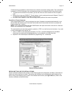
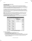
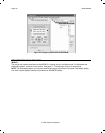
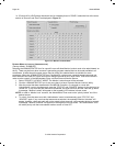
TESTING COMMANDS UNDER POWER MANAGEMENT AND SENSE TRIGGERS
Commands may be tested in the same manner as on the Virtual Keypad. To test commands, the Dragon PC
must be connected to the front panel COM PORT or USB Port and emitters must be placed in the proper
Source and Zone IR Emitter output ports. For Fast Testing, an emitter placed in the COMMON IR port will be
sufficient.
1. Select the Sense Trigger to be tested with the IR codes placed under it to test. The Trigger should now
be hi-lighted.
2. Select the TEST button located in the bottom right-hand side of the Power Management window.
Commands listed under the Macro Command List for that selected sense trigger should now be
executed in order of appearance out of the proper Emitter Ports on the MRC88 Controller.