


Model MRC88 Page: 31
© 2003 Xantech Corporation
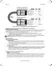
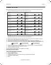
Keypad Address Setting
Application
JP1 JP2
First (or Single) Keypad in Zone
(Primary Keypad connected
directly to MRC88 Controller)
OFF OFF
Second Keypad in Zone
(Connected to Primary
keypads Expansion Port)
OFF ON
Third Keypad in Zone
(Connected to Second
keypads Expansion Port)
ON OFF
Fourth Keypad in zone
(Connected to third keypads
Expansion Port)
ON ON
Table 1 – MRC88 Keypad Address Settings
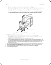
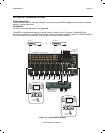
Zone Termination
The LAST keypad connected in the zone (Keypad with no other keypad plugged into its EXPANSION
port) must have the Zone Termination Jumper installed – Figure 5-(18).
Sensor Enable
To disable the Keypads on-board IR Receiver, remove the Sensor Enable jumper on the rear of the
keypad – Figure 5-(19).
External IR Terminal Block
To conveniently add other Xantech IR Receivers or Keypads (SMARTPAD or WATERPAD) in
conjunction with the MRC88 Keypads, you may wire 18AWG-24AWG 4-conductor wire, directly to the
terminal block on the rear of the Keypad – Figure 5-(23). A 4-conductor screw-type removable
connector is provided to safely wire the +12v, STATUS, IR IN and GND to the rear of the Keypad. This
might be useful when adding a Plasma Friendly (or other) IR Receiver (490-90 etc.) or adding a sub-
zone keypad either outdoors or in a bathroom (WATERPAD Keypad).
Note: The 12VDC output terminal is rated at 100mA and can power up to one
SMARTPAD/WATERPAD Keypad or up to 4 IR Receivers. Anymore then this will require the use of an
external power supply. Do not wire the external power supply to the MRC88 keypad. Wire directly
to the units to be powered.
The STATUS line is an output and is active Hi (+12VDC) when the MRC88 Keypad is powered ON and
is LOW (0VDC) when the Keypad is OFF. Use this to provide Bank Tracking LED on the
SMARTPAD/WATERPAD keypad or other.
In Zone IR
To wire local emitters in-the-zone (emitters used to control components in the same general area as the
keypad), wire the IR OUT and GND terminals on the rear of the MRC88 Keypad –Figure 5-(22) to the
IR (white stripe) and GND of the emitter cable. To control numerous components in the same area, wire
these terminals to an amplified connecting block (Xantech 791-44) using 18-20AWG 2-conductor cable.
A 2-conductor screw-type removable connector is provided.
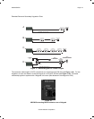
ZONE EXPANSION (CONNECTING TWO MRC88 CONTROLLERS)
(EXPANDED)
For systems greater than 8 Zones, two MRC88 Controller/Amplifiers can be linked together for systems up to
16 Zones. Zone expansion is only available in Advanced programming configurations.