


Page: 20 Model MRC88
© 2003 Xantech Corporation
Section 2: Installation & Connections
INSTALLATION
OPERATION: OUT-OF-THE-BOX PRE TEST
(BASIC/ADVANCED/EXPANDED)
The MRC-88 is shipped to operate basic functions ‘Out-Of-The-Box’ without any programming. Simply by
plugging in keypads via standard CAT-5 RJ45 terminated patch cable and powering the controller ‘on’, you can
control Source Selection, Volume Up/Down and speaker Mute capabilities.
Completing the Out-Of-The-Box Pre-Test will verify that all sources and zone components are working properly
to select and distribute audio and video prior to programming with Dragon Drop-IR™. This will ensure that the
unit is indeed functioning correctly ‘prior’ to fixed installation and allow proper troubleshooting procedures if a
problem is encountered. Instructions regarding full programming for specific components and features will
follow.
Note: For ‘EXPANDED’ configuration, test both units individually as outlined below.
Note: For simplicity of test set-up, only one Source Component, one pair of speakers, and one TV/Video
Monitor will be necessary.
For the pre-test, you will need the following:
8-RJ45 Terminated CAT5 cables. (Pre test cables prior to use – See Caution below)
1-Audio/Video Source Component (i.e. VCR, DVD or other) [Will be used to test ALL Source Inputs]
1 Audio/Video RCA Harness (Capable of Audio Left/Right and Video)
1-Pair of speakers with Speaker Cable properly terminated into a 4 conductor WECO Plug [Will be used to
test Speaker outputs]
1-TV or Video Monitor [Will be used to test ALL Video Outputs]
8-283M Blink Emitter
8-MRC-88 Keypads
MRC-88 Controller/Amplifier
PA435X Two-Zone Stereo Amplifier (or other)
2 Pair of Stereo RCA Phono cables (for PA435X)
AC Cord
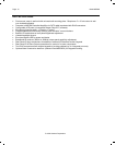
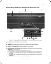
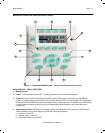
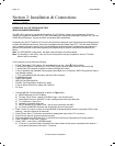
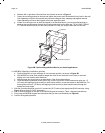
1. Connect MRC88 Controller/Amplifier as shown in Figure 13 to:
a) MRC88 Keypads via CAT5 Cables
b) Pre Amp Out of Zones 7 and 8 to PA435X Zones 1 and 2 Audio Input
c) Audio/Video Source to SOURCE 1 Audio Left/Right and Video Input terminals
d) TV or Monitor to Video Out 1
e) Speakers to Speaker Output #1
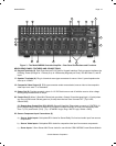
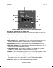
f) All 8 IR emitters to IR Emitter Ports 1 thru 8 (rear connection Item #26)
g) AC Power for MRC88 Controller and Audio/Video Source Component
2. Press “Power On” button on the front of the MRC88 Controller/Amplifier (wait for front panel LED’s to stop
flashing – should be less than 20 seconds).
3. Power ON the Zone 1 TV/monitor and select the appropriate input (on the TV or monitor).
4. Power ON the Source Component and press play.
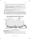
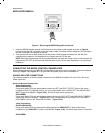
5. Place the emitter from IR Emitter Port 1 near the front of the Source Components IR Sensor window.
6. Press “POWER” on the Zone 1 Keypad.
7. Select “SRC1” on the Zone 1 MRC88 Keypad.
a) If Source 1 is an Audio/Video component, the video content of the source connected to the Source 1
inputs should be seen on the zone 1 TV/monitor.