


Page: 34 Model MRC88
© 2003 Xantech Corporation
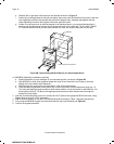
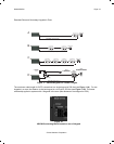
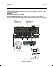
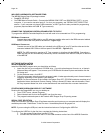
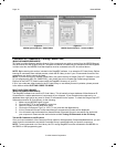
If any keypad in the zone is using an external IR receiver, or if an outdoor keypad is necessary in a sub-
zone, the MRC88 Terminal Block on the rear of the keypad (see Figure 12) can be used to expand the
connections on the back of the keypad as shown in Figures 11A, B, & C. The Maximum cable run to the
external IR receiver/keypad in each of the above cases can be up to 125 feet from the keypad depending
upon type and gauge of wire used.
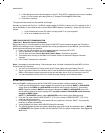
Note: If no MRC-88 Keypad will be used in a particular zone, IR Receivers and/or IR based Keypads may
be used as shown in Figure 11D using the MRC44CB1 Connecting Block. This will be desired for:
1. Zones with IR Receiver ONLY
2. Outdoor Zone where WaterPad Keypad and/or IR Receiver is needed
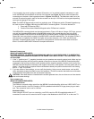
The MRC44CB1 connecting block can be used as shown in Figure 11D above. Using a CAT5 wire, connect
one end into the desired Zone output of the MRC88 controller and connect the other end to the RJ45
connector labeled CONTROLLER on the MRC44CB1 connecting block. IR Receivers terminated with a
Stereo Mini Jack may directly connect to the MRC44CB1 connector labeled IR IN. For all others IR Recv’s
with bare wire or Keypads) use 24AWG or higher and connect using the +12v, GND, and SIG screw
terminals. A separate power supply is required for configurations in which the current load will exceed
85mA. Consult the MRC44CB1 manual for complete instructions.
S
PEAKER CONNECTIONS
(BASIC/ADVANCED/EXPANDED)
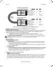
SPEAKER PHASING: TO OBTAIN STABLE IMAGING AND FULL BASS RESPONSE, IT IS IMPERATIVE
THAT STEREO SPEAKERS BE CONNECTED "IN PHASE" WITH EACH OTHER. YOU CAN VERIFY THIS
AS FOLLOWS:
1. If the "+" (positive) and "–" (negative) terminals on your speakers are correctly marked, and visible, and you
have wired the system with the positive speaker connector on the rear of the MRC88 Controller/Amplifier
connected to the positive connector on the speaker and the negative speaker connector on the rear of the
MRC88 Controller/Amplifier connected to the negative connector on the speaker, then the system will be "in
phase". No further action is required. Most manufacturers identify the positive terminal with a red binding
post, a "+" sign, or a red dot.
2. If you are unsure of the markings, you can verify the phasing. Using a mono sound source, such as AM
radio, alternately reverse the leads to one of the speakers. Pick the connection that delivers a solid center
image between the speakers as well as best bass response.
CAUTION: After lead ends are inserted and the screws tightened down, be sure there are no free strands
that could cause shorting!
V
IDEO CONNECTIONS
(BASIC/ADVANCED/EXPANDED)
Composite Video
The buffered, composite video output from the MRC88 Controller/Amplifier will drive a VIDEO INPUT on a
TV or monitor directly. Use RG-6 coaxial or RG-59 quadshield cable with RCA type phono plugs on each
end. This connection can be run for 100 feet.
Modulated Video
When using the RF/ANT input on a television, use RG-6 coaxial or RG-59 quadshield cable with "F"
connectors on each end to connect to the RF output on the Modulator to the RF/ANT in on the zone TV.