


TFA9812_2 © NXP B.V. 2009. All rights reserved.
Preliminary data sheet Rev. 02 — 22 January 2009 46 of 66
NXP Semiconductors
TFA9812
BTL stereo Class-D audio amplifier with I
2
S input
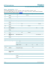
[1] I
P
is the current through the analog supply voltage (V
DDA
) pin added to the current through the power supply voltage (V
DDP
) pin.
[2] Thermal foldback temperature sensor is not located at hottest spot. Hottest spot is 12 °C higher.
[3] Current limiting concept: in overcurrent condition no interruption of the audio signal in case of impedance drop.
[4] PLL output frequency not external available.
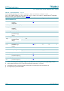
Thermal Foldback (TF)
T
act(th_fold)
thermal foldback
activation
temperature
[2]
118 125 132 °C
OverTemperature Protection (OTP)
T
act(th_prot)
thermal protection
activation
temperature
- - 160 °C
OverVoltage Protection (OVP)
V
P(ovp)
overvoltage
protection supply
voltage
20 22.3 24 V
UnderVoltage Protections (UVP)
V
P(uvp)
undervoltage
protection supply
voltage
UVP on V
DDA
7 7.5 8 V
UVP on V
DDA(3V3)
1.6 2.2 3.0 V
OverCurrent Protection (OCP)
I
O(ocp)
overcurrent
protection output
current
[3]
3.0 3.3 3.6 A
Window Protection (WP)
V
o
output voltage high level - V
DDA
− 1- V
low level - REFA + 1 - V
OverFrequency Protection (OFP)
f
OFP
Overfrequency
protection frequency
At PLL output frequency
[4]
100 140 185 MHz
UnderFrequency Protection (OFP)
f
UFP
Underfrequency
protection frequency
At PLL output frequency
[4]
30 45 60 MHz
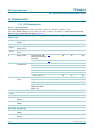
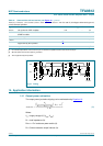
Table 55. DC characteristics
…continued
Unless specified otherwise, V
DDA
=V
DDP
= 12 V, V
SSP1
= V
SSP2
= 0 V, V
DDA(3V3)
=V
DDD(3V3)
= 3.3 V,
V
SS1
=V
SS2
= REFD = REFA = 0 V, T
amb
=25
°
C, R
L
=8
Ω
, f
i
= 1 kHz, f
s
= 44.1 kHz, f
sw
= 400 kHz, 24-bit I
2
S input data,
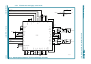
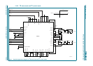
MCLK clock mode, typical application diagram (
Figure 13).
Symbol Parameter Condition Min Typ Max Unit