


TFA9812_2 © NXP B.V. 2009. All rights reserved.
Preliminary data sheet Rev. 02 — 22 January 2009 16 of 66
NXP Semiconductors
TFA9812
BTL stereo Class-D audio amplifier with I
2
S input
In I
2
C control mode the following sample frequency f
s
can be used: 8 kHz, 11.025 kHz,
12 kHz, 16 kHz, 22.05 kHz, 24 kHz, 32 kHz, 44.1 kHz, 48 kHz, 64 kHz, 88.2 kHz, 96 kHz,
128 kHz, 176.4 kHz or 192 kHz. The I
2
C control for f
s
selection can be found in
Section 9.5.7.
In Legacy control mode the following sample frequencies (f
s
) can be used: 32 kHz,
44.1 kHz or 48 kHz.
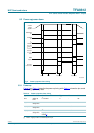
8.4.2 Digital audio data format control
The BCK-to-WS and MCLK-to-WS frequency ratios are automatically detected, so no
control settings need to be configured for these.
In I
2
C control mode all the formats listed in Table 12 are supported. The appropriate I
2
C
controls for selecting the supported formats can be found in Section 9. In the Legacy
control mode only a subset of the supported formats can be used. These are shown in
Table 12 and the required pin control is given in Table 13.
See Section 8.2.1 for details of how to enable Legacy control mode.
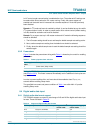
8.5 Digital signal-processing features
8.5.1 Equalizer
8.5.1.1 Equalizer options
The equalizer function can be bypassed and the equalizer can be configured to either a
5-band or 10-band function. These settings are for both audio channels simultaneously.
There are 20 bands in the equalizer. These are distributed as follows:
• Bands A1 to A5 are bands 1 to 5 of output 1 (used in 5-band and 10-band
configuration).
• Bands B1 to B5 are bands 1 to 5 of output 2 (used in 5-band and 10-band
configuration).
• Bands C1 to C5 are bands 6 to 10 of output 1 (used in 10-band configuration only).
• Bands D1 to D5 are bands 6 to 10 of output 2 (used in 10-band configuration only).
In I
2
C control mode each band can be configured separately using I
2
C register settings.
In Legacy control mode the equalizer is bypassed.
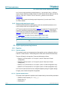
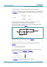
8.5.1.2 Equalizer band function
The shape of each parametric equalizer band is determined by the three filter parameters:
• (Relative) center frequency .
• Quality factor Q.
• Gain factor G.
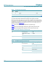
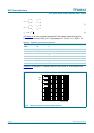
Table 13. Digital audio data format selection in Legacy control mode
SCL/SFOR pin value Interface formats (MSB-first)
0I
2
S
1 MSB-justified
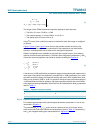
ω 2π f
c
f
s
⁄()=