


TFA9812_2 © NXP B.V. 2009. All rights reserved.
Preliminary data sheet Rev. 02 — 22 January 2009 10 of 66
NXP Semiconductors
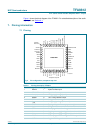
TFA9812
BTL stereo Class-D audio amplifier with I
2
S input
• In Soft mute mode the I
2
S input signal is overruled with a soft mute.
– In Legacy control mode the analog input pin AVOL controls Soft mute mode.
– In I
2
C control mode I
2
C control can be used to enable an automatic soft mute
function. See also Section 8.5.3.
• In Hard mute mode the PWM controller is overruled with a 50 % duty cycle square
pulse. The Hard mute mode is only available in I
2
C control mode.
• In Operating mode the TFA9812 amplifies the I
2
S audio input signal in line with the
actual control setting.
• In 3-state mode the output stages are switched off.
• Fault mode is entered when a fault condition is detected by one or more of the
protection mechanisms implemented in the TFA9812. In Fault mode the actual device
configuration depends on the fault detected: see Section 8.7 for more information.
Fault mode is for a subset of the faults flagged on the DIAG output pin. When the
DIAG pin is flagged the output stages will be forced to enter 3-state mode. In Sleep
mode the DIAG pin will not flag fault modes.
[1] Clocking faults do not trigger DIAG output.
[2] Under these conditions soft mute still has to be enabled by the appropriate I
2
C setting.
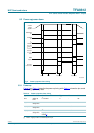
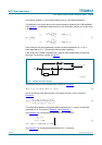
8.2.3 I
2
S master/slave modes and MCLK/BCK clock modes
The I
2
S interface can be set in master or in slave.
• In I
2
S master mode the PLL locks to the output signal of the internal crystal oscillator
circuit which uses an external crystal. The BCK, WS and MCLK signals are generated
by the TFA9812. On the MCLK pin the TFA9812 delivers a master clock running at the
crystal frequency.
• In I
2
S slave mode the PLL can lock to:
– The external MCLK signal on the MCLK pin called MCLK clock mode.
– The I
2
S input BCK signal on the BCK pin called BCK clock mode.
The I
2
S master or slave mode can be selected:
• In I
2
C control mode by selecting the right I
2
C setting.
• In legacy control mode by selecting the right setting on the SDA/MS pin.
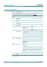
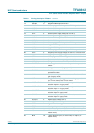
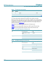
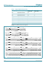
Table 5. Operational mode selection
Pin: DIAG Output Operational mode
selected:
POWERUP ENABLE CSEL AVOL
0 - - - floating Sleep mode
1 - - - 0 / floating Fault mode (enabled by
system)
[1]
1 1 1 - floating Soft mute mode (in I
2
C
control mode)
[2]
1 1 0 < 0.8 V floating Soft mute (in Legacy control
mode)
1 0 - - floating 3-state mode
1 1 - - floating Operational mode