


TFA9812_2 © NXP B.V. 2009. All rights reserved.
Preliminary data sheet Rev. 02 — 22 January 2009 21 of 66
NXP Semiconductors
TFA9812
BTL stereo Class-D audio amplifier with I
2
S input
Section 9 shows the I
2
C address locations for the digital gain control for both channels.
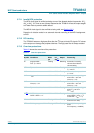
In Legacy mode the pin AVOL (32) can be used to control the volume.
Voltage levels of 0.8 V to 2.8 V correspond linearly to control values of 00h (0 dB) to F9h
(mute). See Table 16.
An external pull-up resistor connected to the V
DDD(3V3)
can be applied to provide a default
volume of 0 dB. Pin AVOL has no function in I
2
C mode.
8.5.3 Soft mute and mute
Soft mute is available in I
2
C and in Legacy control modes: hard mute can be enabled only
in I
2
C control mode.
In I
2
C control mode the soft mute function smoothly reduces the gain setting for both
channels to mute level over a duration of 128/f
s
seconds. The smooth shape is
implemented as a raised cosine function. Soft demute results in a similar gain increase.
This implementation avoids audible plops.
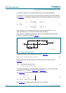
A different soft mute and soft demute function is implemented in Legacy mode. This works
via the analog gain control under the control of pin AVOL. The analog volume control input
signal is first-order low-pass filtered with a time constant of 10 ms in the digital domain.
Suddenly switching on or switching off volume by setting the control voltage to
> 2.8 V or < 0.8 V respectively will result in a fading which lasts approximately 15 ms
(switching between 0 V and 3.3 V at AVOL).
In Legacy mode the soft demute function that is part of the automatic power-up sequence
is similar to the I
2
C mode soft demute function described above. The I
2
C control for the
soft and hard mute functions can be found In Section 9.
8.5.4 Output signal and word-select polarity control
In I
2
C control mode the TFA9812 can switch the polarity of the stereo output signal. The
effect is a 180 degree phase shift of both output signals.
The TFA9812 also has the option of switching the polarity of the WS signal. Without
polarity inversion the left audio signal is connected to channel 1 and the right audio signal
is connected to channel 2.
The I
2
C control for the polarity switch can be found in Section 9.5.1.
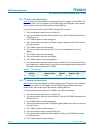
8.5.5 Gain boost and clip level control
An additional gain boost of +24 dB can be selected in the TFA9812. In Legacy mode this
feature can be selected with the GAIN pin, see Table 17.
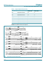
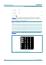
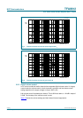
Table 16. Volume control channel suppression table
[7:0] control value (hexadecimal) Gain (dB)
00 0
01 −0.5
... steps of 0.5 dB
F7 −123.5
F8 −124
F9 mute