


TFA9812_2 © NXP B.V. 2009. All rights reserved.
Preliminary data sheet Rev. 02 — 22 January 2009 18 of 66
NXP Semiconductors
TFA9812
BTL stereo Class-D audio amplifier with I
2
S input
(5)
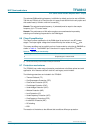
The ranges of the TFA9812 parametric equalizer settings for each band are:
• The Gain, G is from −30 dB to +12 dB.
• The center frequency, f
c
is from 0.0004 * f
s
to 0.49 * f
s
.
• The quality factor Q is from 0.001 to 8.
Using I
2
C control, filter coefficients need to be entered for each filter stage to configure it
as desired.
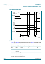
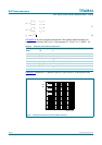
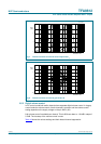
Figure 6, Figure 7 and Figure 8 show some of the possible transfer functions of the
equalizer bands. The relations are symmetrical for the suppression and amplification
functions. A skewing effect can be observed for the higher frequencies.
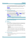
Different configurations are available for the same filter transfer function, thus allowing
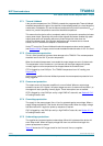
optimum numerical noise performance. The binary filter configuration parameters t
1
and t
2
control the actual configuration and should be chosen according to Equation 6.
(6)
A maximum of 12 dB amplification per equalizer stage can be achieved with respect to the
input signal. Each band of the equalizer is provided with a −6 dB amplification, so in order
to prevent numerical clipping for some filter settings with over 6 dB of amplification, band
filters can be scaled by 0 dB or −6 dB. For optimum numerical noise performance steps of
−6 dB amplification should be applied to the highest possible sections that are still within
scale signal processing safeguards. Band filters can be scaled with the binary parameters
listed in Table 14.
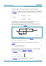
8.5.1.3 Equalizer band control
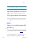
For compact representation with positive signed parameters, parameters k
1
’ and k
2
’ are
introduced in Equation 7.
The parameters k
0
, k
1
', k
2
', t
1
, t
2
and s must be combined in two 16-bit control words,
word1 and word2, and must fit within the representation given in Table 15. Parameters k
1
'
and k
2
' are unsigned floating-point representations in Equation 8.
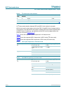
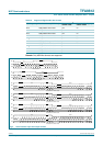
Table 14. Equalizer scale factor coding
s scale factor (dB)
00
1 −6
K
0
G=
K
1
ωcos–=
K
2
2Q ωsin–()2Q ωsin+()⁄=
G1≥
t
1
0 ω<=π 2⁄
1 ω>π 2⁄
=
t
2
0k
2
>=0
1k
2
<0
=