


TFA9812_2 © NXP B.V. 2009. All rights reserved.
Preliminary data sheet Rev. 02 — 22 January 2009 17 of 66
NXP Semiconductors
TFA9812
BTL stereo Class-D audio amplifier with I
2
S input
In the above equation f
c
is the center frequency and f
s
is the sample frequency.
The definition of the quality factor is the center frequency divided by the 3 dB bandwidth,
see Equation 1. In parametric equalizers this is only valid when the gain is set very small
(−30 dB).
(1)
Each band filter can be programmed to perform a band-suppression (G < 1) or a
band-amplification (G > 1) function around the center frequency.
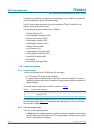
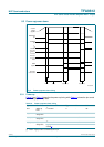
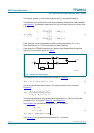
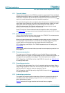
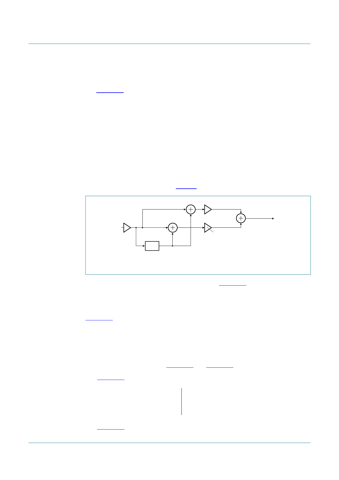
Each band of the TFA9812 equalizer has a second-order Regalia-Mitra all-pass filter
structure. The structure is shown in Figure 5.
The transfer function of this all-pass filter is shown in Equation 2:
(2)
A(z) is the second-order filter structure. The transfer function of A(z) is shown in
Equation 3:
(3)
The relationship between the programmable parameters K
0
, K
1
, and K
2
and the filter
parameters G, ω, Q is shown in Equation 4 and Equation 5.
Use Equation 4 to calculate band suppression (G < 1) functions.
(4)
Use Equation 5 to calculate band amplification (G ≥ 1) functions.
Fig 5. Regalia filter flow-diagram
Q
f
c
f
2
f
1
–
-----------------
;=
f
1
: 20
10
A
f
1
A
f
c
--------
log 3dB f
c
f
1
>=
f
2
: 20
10
A
f
2
A
f
c
--------
log 3dB f
2
f
c
>,=
½
X(z)
A(z)
s
Y(z)
+
+
+
−
010aaa406
K
0
/2
Hz() 12⁄ 1Az()+()K
0
2⁄ 1Az()–()⋅+⋅=
Az()
K
1
K
2
1K
1
+()Z
1–
Z
2–
+⋅⋅+
1K
2
1K
1
+()Z
1–
K
1
Z
2–
⋅+⋅⋅+
---------------------------------------------------------------------------------
=
K
0
G=
K
1
ωcos–=
K
2
2Q G ωsin–⋅()2Q G ωsin+⋅()⁄=
G1<