


TFA9812_2 © NXP B.V. 2009. All rights reserved.
Preliminary data sheet Rev. 02 — 22 January 2009 31 of 66
NXP Semiconductors
TFA9812
BTL stereo Class-D audio amplifier with I
2
S input
9.5.1 Interpolator settings and soft mute
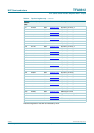
9.5.2 Volume control
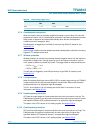
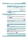
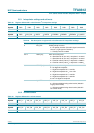
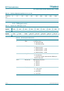
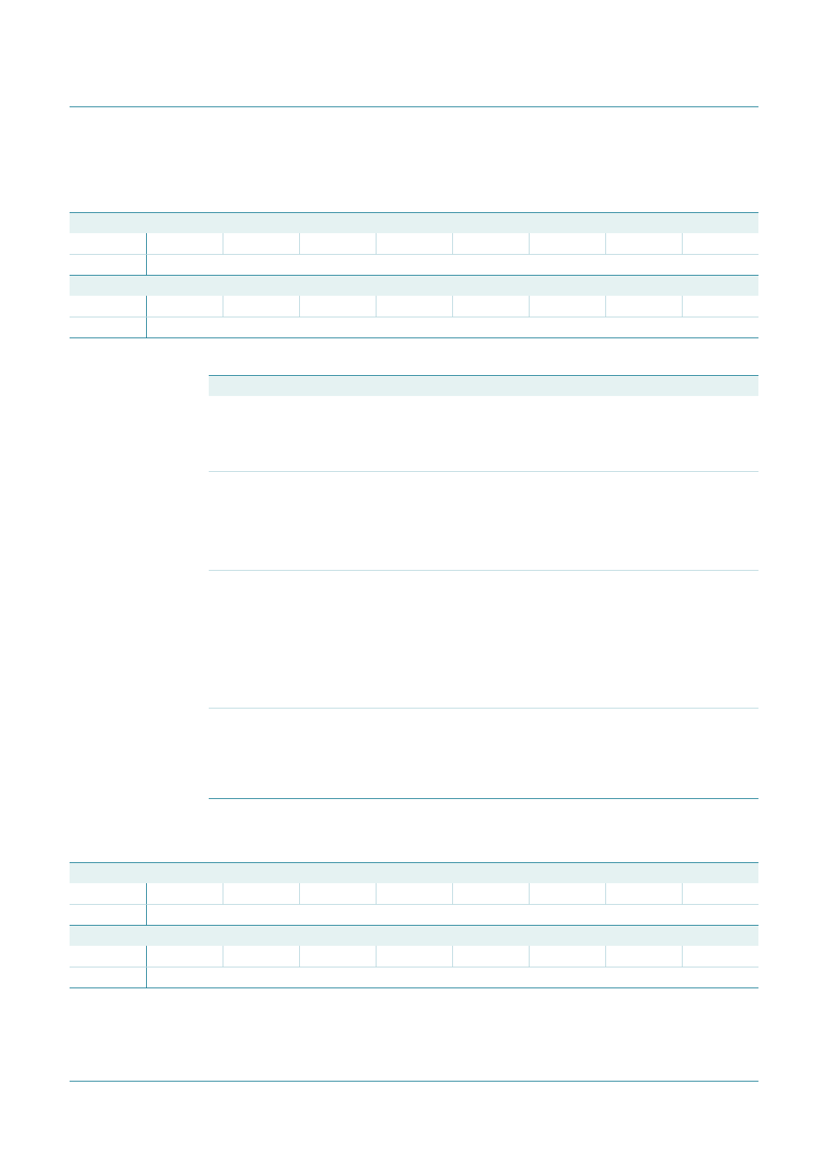
Table 28. Register address 00h: miscellaneous I
2
C interpolator settings
Bit 15 14 13 12 11 10 9 8
Symbol RSD RSD RSD RSD RSD RSD RSD RSD
Default 00000000
Bit 7 6 5 4 3 2 1 0
Symbol RSD INV_POL ROFF1 ROFF0 FDEMP2 FDEMP1 FDEMP0 S_MUTE
Default 00100001/0
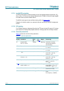
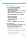
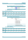
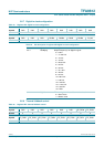
Table 29. Bit description of register 00h: miscellaneous I
2
C interpolator settings
Bit Symbol Description
6 INV_POL Enable polarity inversion:
0 = No polarity inversion (left audio signal connected to
channel 1; right signal to channel 2)
1 = Polarity inversion enabled
5 to 4 ROFF[1:0] Filter roll-off sharpness:
0 = Slow filter roll-off (2 to 8 f
s
) ≥ stop band > 0.7619 f
s
1 = Slow filter roll-off (2 to 8 f
s
) ≥ stop band > 0.7619 f
s
2 = Fast filter roll-off (2 to 8 f
s
) ≥ stop band > 0.6094 f
s
3 = Fast filter roll-off (2 to 8 f
s
) ≥ stop band > 0.6094 f
s
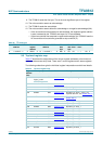
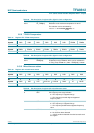
3 to 1 FDEMP[2:0] Digital de-emphasis setting:
0 = No digital de-emphasis
1 = Digital de-emphasis for f
s
= 32 kHz
2 = Digital de-emphasis for f
s
= 44.1 kHz
3 = Digital de-emphasis for f
s
= 48 kHz
4 = Digital de-emphasis for f
s
= 96 kHz
5 to 8 = No digital de-emphasis
0 S_MUTE Soft mute:
0 = Soft mute disabled using raised cosine (default in
Legacy control mode)
1 = Soft mute enabled using raised cosine (default in
I
2
C control mode)
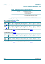
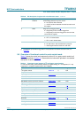
Table 30. Register address 01h: volume control
Bit 15 14 13 12 11 10 9 8
Symbol VOL_L7 VOL_L6 VOL_L5 VOL_L4 VOL_L3 VOL_L2 VOL_L1 VOL_L0
Default 00000000
Bit 7 6 5 4 3 2 1 0
Symbol VOL_R7 VOL_R6 VOL_R5 VOL_R4 VOL_R3 VOL_R2 VOL_R1 VOL_R0
Default 00000000