


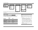
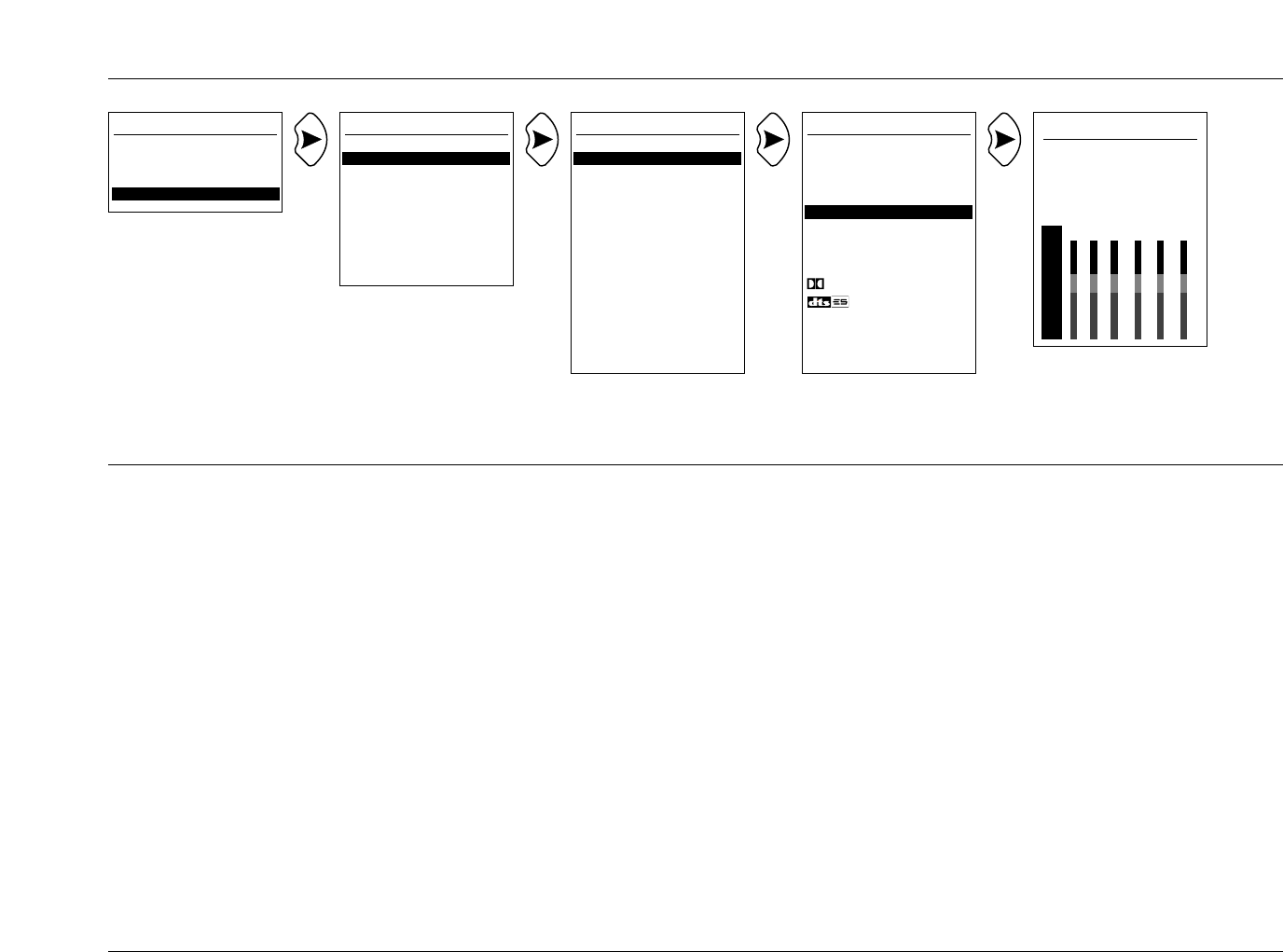
DVD1 ANLG IN LVL
AUTO ON
MANUAL +0dB
AUTO GAIN +0.0dB
dB L C R SL SR LFE
0
-6
-15 XXX XX X
-30
-45
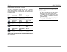
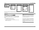
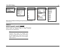
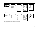
DVD1 INPUT SETUP
NAME DVD1
DIGITAL IN COAX-1
ANALOG IN NONE
ANLG IN LVL AUTO
VIDEO IN S-VIDEO-1
COMPONENT IN 1
2-CH L7 FILM
D 5.1 L7 FILM
dts L7 FILM
MAIN ADVANCED
ZONE2 ADVANCED
RECORD ADVANCED
3-7
The SETUP Menu
SDP-40
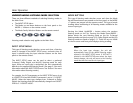
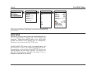
levels. When the signal is too high, ANLG IN LVL is quickly
decreased to avoid overload. When the signal is too low, ANLG IN
LVL is slowly increased to maximize the signal-to-noise ratio and
dynamic range. The AUTO parameter setting will never exceed the
current MANUAL parameter setting. The current AUTO parameter
setting is shown in the INPUT GAIN parameter. When the AUTO
parameter is set to OFF, the ANLG IN LVL parameter can be
adjusted manually.
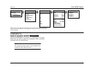
MANUAL (-18 to +12dB)
MANUAL provides manual adjustment of analog input levels in the
Main Zone when the AUTO parameter is set to OFF. When
MANUAL is selected, a white horizontal bar graph will appear on
the screen below the parameter. This graph illustrates the position
at which the current setting falls within the -18 to +12dB
parameter range. Press the up and down MENU arrows to increase
and decrease the setting in 1dB increments. Press the left MENU
arrow to close the graph and return to the ANLG IN LVL menu.
The current setting is shown in the MANUAL and INPUT GAIN
parameters. When switching from AUTO to MANUAL adjustment,
the INPUT GAIN parameter will continue to reflect the last AUTO
setting until the MANUAL setting is adjusted.
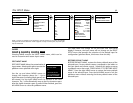
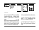
The level meters in the lower-left corner indicate fluctuating input
levels in the left (L) and right (R) channels. These meters indicate
signal levels for the selected input, whether the input signal is
analog or digital. For example, if the input signal is digital only, the
level meters will indicate the digital input signal levels.
These level meters appear in combinations of green, yellow, and
red on the blue-screen background. Green indicates normal input
levels; yellow indicates the onset of overload; and red
indicates overload. The yellow arrow to the right of each bar
indicates the current input peak level. The INPUT GAIN parameter
also shows the current input level, whether AUTO or MANUAL is
selected.
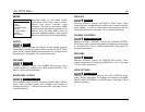
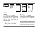
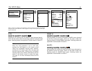
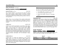
MAIN MENU
MODE ADJUST
AUDIO CONTROLS
SETUP
INPUT SETUP
DVD1
DVD2
LD
TV
SAT
VCR
CD
PVR
GAME
TAPE
TUNER
AUX
SETUP
INPUTS
SPEAKERS
REAR PANEL CONFIG
DISPLAYS
VOLUME CONTROLS
TRIGGERS
LOCK OPTIONS
DVD1 is used as an example in this illustration, and will continue to be used as an example
throughout this section. Whenever “DVD1” appears as a step in a menu path, any other input
may be substituted.