217
18 CPU Baseboard: Description/Setting
Configuration Jumpers
This chapter describes the CPU baseboard and tells how to use the jumpers.
Warnings and Cautions
Only a qualified service technician is authorized to remove the server covers and to access any
of the components inside the server. Before removing the covers, see “Safety Guidelines” on
page 115.
CPU Baseboard Features
The CPU baseboard interfaces with the PHP I/O baseboard and memory modules through the
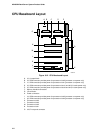
midplane. The CPU baseboard provides
• four Slot 2 type connectors for processors packaged in Single Edge Contact (S.E.C.) cartridges
• an onboard DC-to-DC converter that supplies V
TT
voltage for the CPU baseboard and memory
modules
• four sockets for VRM8.3 converters that supply core voltage for the processors
• two sockets for VRM8.3 converters that supply L2 cache voltage for the processors
• I
2
C, serial peripheral interface (SPI), and in-system programming (ISP) server management
interfaces
In a symmetric multiprocessor (SMP) environment, all processors are equal and have no
preassigned tasks. Distributing the processing loads among processors increases server
performance. This is particularly useful when application demand is low and the I/O request load
is high. In an SMP environment, the processors share a common bus, the same interrupt structure,
and access to common memory and I/O channels. The SMP implementation conforms to the
Multiprocessor Specification Version 1.4.
The onboard PCI and memory controller (PMC) supports from 128 MB to 8 GB of ECC memory,
either fast page mode (FPM) or extended data out (EDO) 3.3 V 50 or 60 ns DRAMs, mounted on
JEDEC DIMMs.
Processors
The processor core and L2 cache components are mounted inside the S.E.C. cartridge. It plugs
into one of the four Slot 2 connectors on the CPU baseboard.


