Chapter 13 Server Components: Removing/Reinstalling
137
Processor
The CPU baseboard supports up to four processors packaged in S.E.C. cartridges.
CAUTION
The processors can be extremely sensitive to ESD and always require careful
handling. After removing a processor from a protective wrapper or from the
CPU baseboard, place it on a nonconductive, static-free surface. Do not
slide the processor over any surface.
Removing a Processor
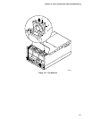
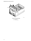
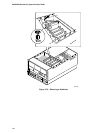
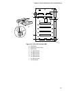
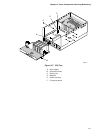
See Figures 13-5.
1. Observe the precautions on page 115, “Safety Guidelines.”
2. Remove the top cover as described in Chapter 12, “Server Covers: Removing/Reinstalling.”
3. Loosen the holddown bracket captive screw and remove the holddown bracket.
4. Simultaneously rotate the eject/insert levers of the processor cartridge outward to eject the
cartridge out of the slot 2 connector on the CPU baseboard.
5. Slide the cartridge out of the slot guides, and place it heat sink-side up on a nonconductive,
static-free surface, or store it in an antistatic protective wrapper.
CAUTION
If a slot 2 connector is depopulated, a terminator module must be installed in
the connector to properly terminate the signals on the FSB.
Installing a Processor
See Figures 13-5.
1. Observe the precautions on page 115, “Safety Guidelines.”
2. Remove the top cover as described in Chapter 12, “Server Covers: Removing/Reinstalling.”
3. Remove the processor cartridge or terminator module as described earlier.
4. Being careful not to touch the gold edge connector on the processor cartridge, remove it from
the protective wrapper. Place the cartridge heat sink-side up on a nonconductive, static-free
surface.
5. Record the serial number of the cartridge in your equipment log.
6. Grasp the cartridge by the eject/insert levers, and carefully slide it into the slot guides until the
levers engage with the flanges in the front sides of the guides.
7. Simultaneously rotate the levers inward until they are flush with the edge of the cartridge to
seat the cartridge into the slot 2 connector on the CPU baseboard.
8. Insert the hook end of the holddown bar in the flange of the right slot guide.
9. Tighten the captive screw.
10. Reinstall the top cover as described in Chapter 12.


