AC450NX Rack Server System Product Guide
138
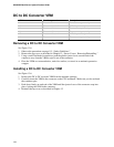
DC to DC Converter VRM
VRM in connector Provides power for Description
J1 Processor #1 Processor core power only
J2 Processor #1 and #2 L2 Cache power only
J3 Processor #2 Processor core power only
J4 Processor #3 Processor core power only
J5 Processor #3 and #4 L2 Cache power only
J6 Processor #4 Processor core power only
Removing a DC to DC Converter VRM
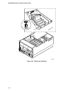
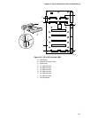
See Figure 13-6.
1. Observe the precautions on page 115, “Safety Guidelines.”
2. Remove the top cover as described in Chapter 12, “Server Covers: Removing/Reinstalling.”
3. Using a small flat-bladed screwdriver, push the plastic ejector levers on each end of the
connector away from the VRM to eject it out of the connector.
4. Place the VRM on a nonconductive, static-free surface, or store it in an antistatic protective
wrapper.
Installing a DC to DC Converter VRM
See Figure 13-6.
1. Remove the DC to DC converter VRM from the antistatic package.
2. Carefully insert the VRM in the connector on the CPU baseboard. Make sure you do not bend
the connector pins.
3. Push down firmly on each end of the VRM until the ejector levers of the connector snap into
place, locking the VRM in the connector.
4. Reinstall the top cover as described in Chapter 12.


