AC450NX Rack Server System Product Guide
146
Add-in Boards
The PHP I/O baseboard provides 10 PCI bus master slots and one ISA bus master slot. They
accept any add-in PCI and ISA boards or any add-in board that is compatible with an IBM PC AT
†
or PC XT
†
system (except for an 8-bit drop card that fits only in an 8-bit PC XT connector). One
PCI slot shares a common chassis I/O expansion slot with the ISA slot; you can use the slot for
either PCI or the ISA, but not both.
CAUTION
Some accessory/option card outputs may exceed Class 2 or limited power
source limits and must use appropriate interconnecting cabling in
accordance with the National Electric Code during installation.
Do not overload the PHP I/O baseboard by installing add-in boards that draw
excessive current. For expansion slot current limitations, see Chapter 20,
“Power System: Description/Calculating Power Usage.”
Add-in boards can be extremely sensitive to ESD and always require careful
handling. After removing the board from the protective wrapper or from the
baseboard, place it component-side up on a nonconductive, static-free
surface. Do not slide the board over any surface.
✏
NOTE
If you are installing or removing an ISA add-in board , you must run the
SSU to reconfigure the server. Running the SSU is optional for a PCI add-in
board.
Installing an Add-in Board
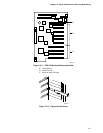
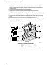
See Figures 13-11, 13-12, and 13-13.
1. Observe the precautions on page 115, “Safety Guidelines.”
2. Remove the top and PCI bus regular slot covers as described in Chapter 12, “Server Covers:
Removing/Reinstalling.”
✏
NOTE
The 64-bit PCI hot swap expansion slots also have a power enabling switch
actuator. This actuator must be installed (unless override is set in the BIOS
setup or an expansion board is installed). The actuator is held in place by the
expansion slot cover screw.
3. Select the appropriate 16-bit ISA, 32-bit PCI, or 64-bit PCI expansion slot. Remove and save
the expansion slot cover and, if installed, the power enabling switch actuator.


