AC450NX Rack Server System Product Guide
148
5. Being careful not to touch the components or gold edge connectors on the add-in board,
remove it from the protective wrapper, and place it component-side up on a nonconductive,
antistatic surface.
6. Record the serial number of the board in your equipment log.
7. Set any jumpers or switches according to the board manufacturer’s instructions.
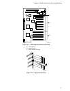
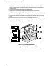
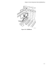
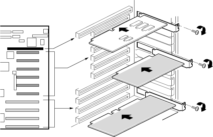
8. Grasp the board by the top edge or upper corners, and firmly press it into an expansion slot
on
the PHP I/O baseboard (Figures 13-13). The tapered foot of the board retaining bracket must
fit into the mating slot in the expansion slot frame.
9. Secure the add-in board to the expansion slot frame using the expansion slot cover retaining
screw.
10. Reinstall the top and PCI bus regular slot covers as described in Chapter 12.
11. If you installed an ISA add-in board, run the SSU to reconfigure the server. Running the SSU
is optional for a PCI add-in board. For information about running this utility, see Chapter 5,
“System Setup Utility: When to Run.”
OM07331
B
A
C
Figure 13-13. Installing an Add-in Board
A. 16-bit ISA slot (ISA board component-side up)
B. 32-bit PCI slot (PCI board, component-side down)
C. 64-bit hot swap PCI slot (PCI board, component-side down)


