


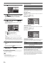
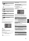

Graphical user interface (GUI) menu
94 En
■ Decoder Mode (Default decoder mode)
Use this feature to designate the default decoder mode (see page 82)
for the input sources when you turn on the power of this unit.
■ EXTD Surround
(Default extended surround decoder mode
setting)
Use this feature to designate the extended surround decoder mode
(see page 72) for the input sources connected to the DIGITAL
INPUT jacks when you turn on the power of this unit.
■ Memory Guard (Memory guard)
Use this feature to prevent accidental changes to sound field
program parameter values and other system settings.
y
When you select the protected parameter, “ ” appears at the bottom left of the GUI
screen. You can adjust the parameters when you select the parameter and “ ” does not
appear at the bottom left of the GUI menu even if “Memory Guard” is set to “On”.
■ HDMI Set (HDMI settings)
Use this feature to adjust the HDMI support audio.
Support Audio (Support audio)
Use this feature to select whether to play back HDMI audio signals
on this unit or on another HDMI component connected to the
HDMI OUT jacks on the rear panel of this unit.
Available audio/video signals depend on the specification of the connected video
monitor. Refer to the instruction manual of each connected component.
Standby Through (Standby through)
Use this feature whether this unit allows the HDMI signals input at
the HDMI IN jacks to pass thorough this unit when this unit is in the
standby mode. You can also designate an HDMI IN jack and an
HDMI OUT jack that accept the signals when “Standby Through” is
set to “On” and this unit is in the standby mode.
• When “Standby Through” is set to “On” and this unit is in the standby mode, the
audio signals are only output at the HDMI OUT 1 or HDMI OUT 2.
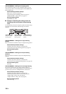
• When “Standby Through” is set to “On”, the amount of power consumption in the
standby mode is increase. When not planning to use this unit for long periods of time,
press
B
MASTER ON/OFF to release it outward to the OFF position to turn off this
unit.
Input/output jack select
When “Standby Through” is set to “On”, you can designate an
HDMI IN jack and an HDMI OUT jack that accept the signals when
this unit in the standby mode.
Input (HDMI IN jack select)
Use this feature to select an HDMI IN jack select that accepts
HDMI signals when this unit is in the standby mode.
Output (HDMI OUT jack select)
Use this feature to select an HDMI OUT jack select that
outputs HDMI signals when this unit is in the standby mode.
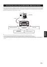
■ Trigger Output (Trigger output)
Use this feature to select the functions of each TRIGGER OUT jack
on this unit.
Trigger operation mode
Choice Functions
Auto
Automatically detects the type of input signals and select
the appropriate decoder mode setting.
Last
Automatically selects the last decoder mode setting used
for the connected input source.
Choice Functions
Auto
Automatically detects the input digital audio signals and
activates the appropriate decoder.
Last
Selects the last selected extended surround decoder
mode.
Choice Functions
Off
Turns off the “Memory Guard” feature.
On
Protects the following parameters:
– sound field program parameters
– GUI menu parameters
– speaker levels settings
Choice Functions
DSP-Z11
Plays back HDMI audio signals on this unit. The HDMI
audio signals input at the HDMI input jacks on this unit
are not output to the HDMI component connected to the
HDMI OUT jacks on the rear panel of this unit.
Other
Plays back HDMI audio signals on another HDMI
component connected to the HDMI OUT jacks.
Note
Choice Functions
Off
Does not accept the HDMI signals when this unit is in the
standby mode.
On
Accepts the HDMI signals when this unit is in the
standby mode.
Notes
Choice Selected HDMI IN jack
IN1
HDMI IN1
IN2
HDMI IN2
IN3
HDMI IN3
IN4
HDMI IN4
FRONT
Front HDMI IN
Choice Selected HDMI OUT jack
OUT 1
HDMI OUT1
OUT 2
HDMI OUT2
Choice Function
Trigger1
Sets the functions for the TRIGGER OUT 1 jack.
Trigger2
Sets the functions for the TRIGGER OUT 2 jack.
Choice Descriptions
Power
Select this setting to send the voltage signals at the
selected TRIGGER OUT jack while the selected zone is
turned on.
Source
Select this setting to send the voltage signals at the
selected TRIGGER OUT jack while the selected input
source is selected.
Manual
Select this setting to send the voltage signals manually.