


www.ti.com
TMS320C6727,TMS320C6726,TMS320C6722
Floating-PointDigitalSignalProcessors
SPRS268E–MAY2005–REVISEDJANUARY2007
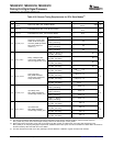
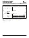
Table4-32.Additional
(1)
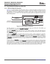
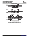
SPISlaveTimings,5-PinOption
(2)(3)
NO.MINMAXUNIT
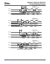
RequireddelayfromSPIx_SCSassertedatslavetofirst
25t
d(SCSL_SPC)S
Pns
SPIx_CLKedgeatslave.
Polarity=0,Phase=0,
0.5t
c(SPC)M
+P+10
fromSPIx_CLKfalling
Polarity=0,Phase=1,
P+10
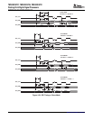
Requireddelayfromfinal
fromSPIx_CLKfalling
26t
d(SPC_SCSH)S
SPIx_CLKedgebeforens
Polarity=1,Phase=0,
SPIx_SCSisdeasserted.
0.5t
c(SPC)M
+P+10
fromSPIx_CLKrising
Polarity=1,Phase=1,
P+10
fromSPIx_CLKrising
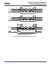
DelayfrommasterassertingSPIx_SCStoslavedriving
27t
ena(SCSL_SOMI)S
P+10ns
SPIx_SOMIvalid
DelayfrommasterdeassertingSPIx_SCStoslave3-stating
28t
dis(SCSH_SOMI)S
P+10ns
SPIx_SOMI
DelayfrommasterdeassertingSPIx_SCStoslavedriving
29t
ena(SCSL_ENA)S
15ns
SPIx_ENAvalid
Polarity=0,Phase=0,
2P+15
fromSPIx_CLKfalling
Polarity=0,Phase=1,
Delayfromfinalclockreceive
2P+15
fromSPIx_CLKrising
edgeonSPIx_CLKtoslave
30t
dis(SPC_ENA)S
ns
3-statingordrivinghigh
Polarity=1,Phase=0,
2P+15
SPIx_ENA.
(4)
fromSPIx_CLKrising
Polarity=1,Phase=1,
2P+15
fromSPIx_CLKfalling
(1)TheseparametersareinadditiontothegeneraltimingsforSPIslavemodes(Table4-26).
(2)P=SYSCLK2period
(3)FigureshowsonlyPolarity=0,Phase=0asanexample.Tablegivesparametersforallfourslaveclockingmodes.
(4)SPIx_ENAisdrivenlowafterthetransmissioncompletesiftheSPIINT0.ENABLE_HIGHZbitisprogrammedto0.Otherwiseitis
3-stated.If3-stated,anexternalpullupresistorshouldbeusedtoprovideavalidleveltothemaster.Thisoptionisusefulwhentying
severalSPIslavedevicestoasinglemaster.
PeripheralandElectricalSpecifications 88SubmitDocumentationFeedback