


www.ti.com
4.18Phase-LockedLoop(PLL)
4.18.1PLLDevice-SpecificInformation
1
0
PLLEN
(PLL_CSR[0])
Divider
D0
(/1 to /32)
PLLREF
PLL
x4 to x25
PLLOUT
Divider
D1
(/1 to /32)
SYSCLK1
CPU and Memory
Divider
D2
(/1 to /32)
SYSCLK2
Peripherals and dMAX
Divider
D3
(/1 to /32)
SYSCLK3
EMIF
AUXCLK
McASP0,1,2
Clock
Input
from
CLKIN or
OSCIN
TMS320C6727,TMS320C6726,TMS320C6722
Floating-PointDigitalSignalProcessors
SPRS268E–MAY2005–REVISEDJANUARY2007
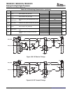
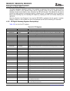
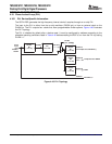
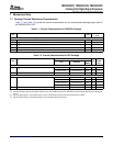
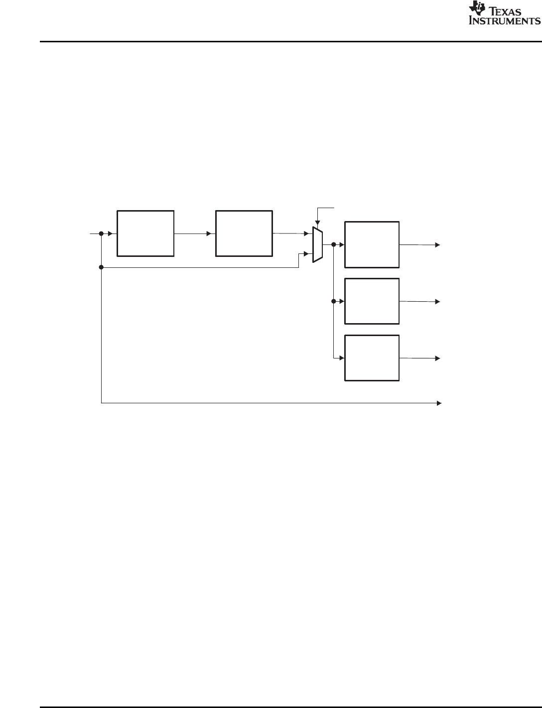
TheC672xDSPgeneratesthehigh-frequencyinternalclocksitrequiresthroughanon-chipPLL.
TheinputtothePLLiseitherfromtheon-chiposcillator(OSCINpin)orfromanexternalclockonthe
CLKINpin.ThePLLoutputsfourclocksthathaveprogrammabledivideroptions.Figure4-43illustrates
thePLLTopology.
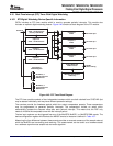
ThePLLisdisabledbydefaultafteradevicereset.Itmustbeconfiguredbysoftwareaccordingtothe
allowableoperatingconditionslistedinTable4-40beforeenablingtheDSPtorunfromthePLLbysetting
PLLEN=1.
Figure4-43.PLLTopology
102PeripheralandElectricalSpecificationsSubmitDocumentationFeedback