


WFM 90 and WFM 91 Service Manual
6–5
Removal and Replacement
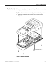
This section contains the instructions on how you can remove and replace the
customer replaceable modules and parts of the WFM 90 or WFM 91 Handheld
Waveform, Vector, Picture, and Audio Monitor.
CAUTION. To prevent damage to the instrument, disconnect the power adapter
and remove installed batteries from the monitor before starting disassembly. See
Batteries on page 6–21.
To prevent damage to the instrument, be sure to follow the preparation instruc-
tions on page 6–2.
Tools Required
Use the tools in Table 6–1 to disassemble the instrument to its individual
modules. Some of these tools are required only for removal of specific instru-
ment components.
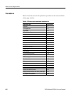
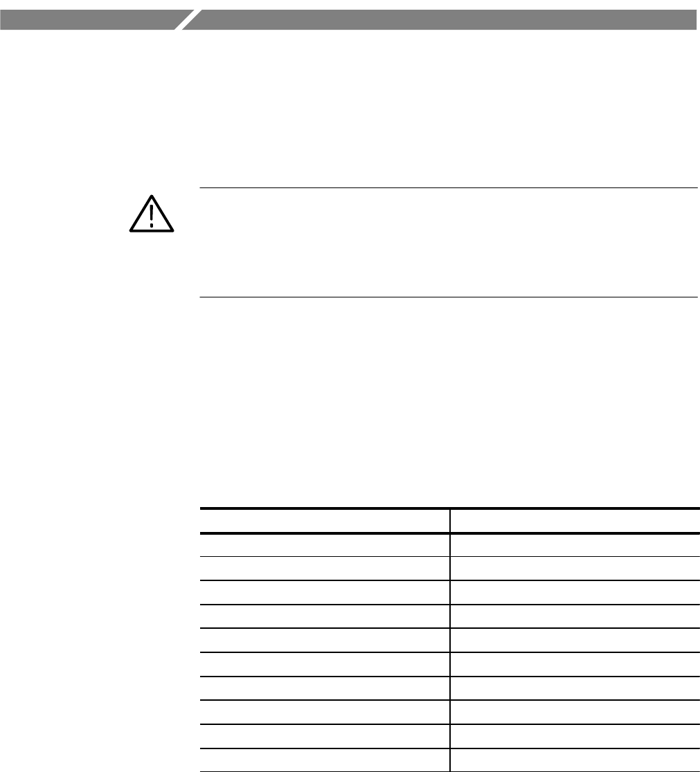
Table 6–1: Tools required for module removal
Name Description
Torx screwdriver handle Accepts Torx-driver bits
T-10 Torx tip Torx-driver bit for T-10 size screw heads
#1 point Philips tip
9/16” hexagonal driver Deep socket
1/4” hexagonal driver
Flat blade screwdriver
Tweezers or needle-nose pliers
Cleaners See Cleaning on page 6–3
Soldering iron 40 W
Solder 2% RMA flux content solder