


Troubleshooting Procedures
WFM 90 and WFM 91 Service Manual
6–35
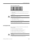
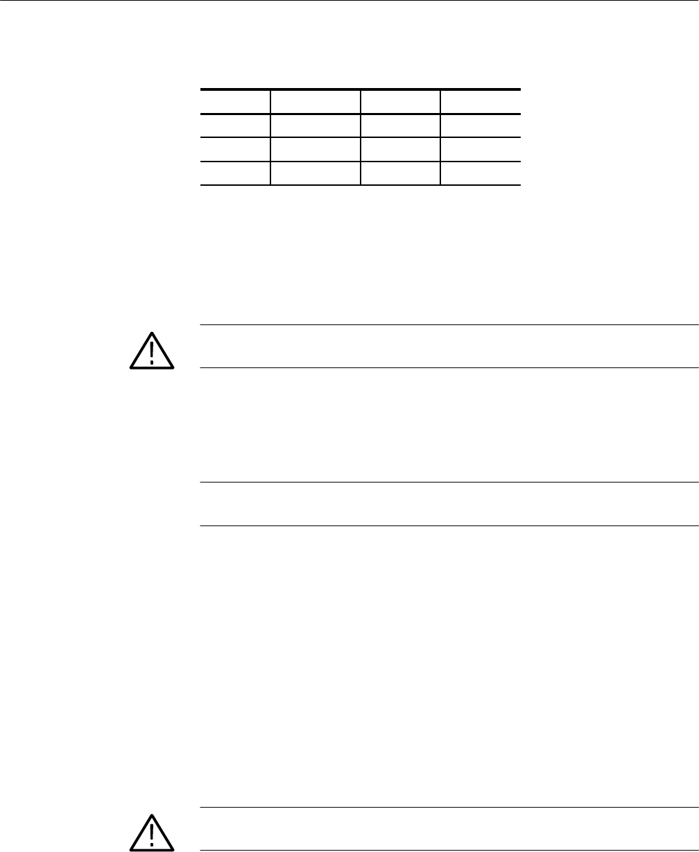
Table 6–4: Low-voltage power supplies
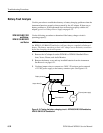
Supply Test Point Output Ripple
+8 V J9, pin 13 "40 mV 30 mV
–8 V J9, pin 14 "40 mV 30 mV
+5 V J9, pin 15 "25 mV 60 mV
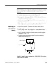
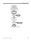
6. If the low-voltage power supplies are operating properly, proceed to Fault
Symptom Table.
7. If any of the voltages are out of specification, check the two fuses on the
Bottom board.
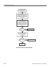
CAUTION. Do not use a soldering iron larger than 18 W or you may damage the
circuit board and the surrounding circuitry.
8. If a fuse is bad, remove the AC adapter and replace the fuse before you retest
the low-voltage power supplies.
9. If both of the fuses are ok, replace the Bottom board.
NOTE. Be sure to remove all modules one at a time to isolate the Bottom board in
cases where a supply might be excessively loaded.
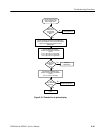
Fault Symptom Table
Be sure to check the low-voltage power supplies before proceeding with the
following procedure:
1. Disconnect the AC adapter from the instrument.
2. Remove any installed batteries. See Batteries on page 6–21.
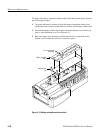
3. Remove the top cover. See Top Cover on page 6–7.
4. Remove the bottom cover. See Bottom Cover on page 6–23.
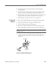
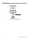
CAUTION. To avoid breaking the circuit boards, do not tighten the circuit board
vise too tightly.
5. Secure the instrument circuit boards in the circuit board vise.