


Performance Verification
WFM 90 and WFM 91 Service Manual
4–7
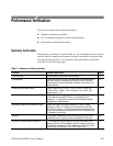
This procedure verifies the following requirement:
1 Volt Full Scale: 1 V input displayed within 1% of 140 IRE (1.00 V PAL).
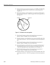
X5 Gain: Gain accuracy within 5% with 1 V input signal. X5 Gain Registration:
v1 major division of vertical shift from baseline between unmagnified and
magnified signal.
1. Set the multiburst generator controls to Composite and Multiburst.
2. Position the signal baseline to the graticule baseline, and then select
X5 GAIN from the Operating menu.
3. Check that the signal baseline is within "1 major division of the graticule
baseline.
4. Select X1 GAIN from the Operating menu.
5. Remove the signal and terminator from the VIDEO IN connector.
6. Connect the output of the VAC to the VIDEO IN connector. Do not
terminate the input.
7. Set the VAC for a 999.9 mV output, with all of the buttons out except for
+LUM and NTSC (PAL button for the WFM 91).
8. Check for a display amplitude of 140 IRE "1.4 IRE (1000 mV "10 mV
PAL).
9. Set the VAC for a 199.9 mV output.
10. Select X5 GAIN from the Operating menu.
11. Check for a display amplitude of 140 IRE "5 IRE (1000 mV "50 mV
PAL).
12. Select X1 GAIN from the Operating menu.
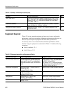
This procedure verifies the following requirement:
Variable Gain Range: Input signals between 0.8 V and 2 V can be adjusted to
140 IRE (1.0 V) display. 160 mV and 400 mV for X5 Gain. Vertical Position
Range: 1 V signal can be positioned so that peak white and sync tip can be
placed at blanking level, with the DC Restorer Clamp on, regardless of gain
setting.
1. Set the VAC for a 999.9 mV output.
2. Select VAR GAIN ON from the Configuration menu.
3. Check by adjusting the Variable Gain controls that the signal amplitude can
be displayed less than 70 IRE (500 mV PAL).
Vertical Gain and Vertical
Magnifier Registration
Variable Gain Range and
Vertical Position Range