


Troubleshooting Procedures
6–50
WFM 90 and WFM 91 Service Manual
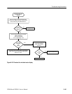
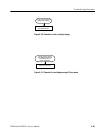
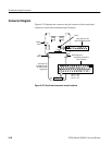
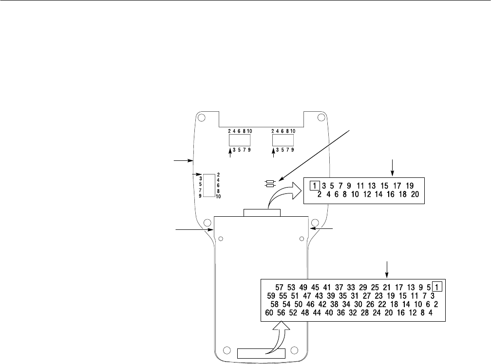
Connector Diagram
Figure 6–32 illustrates the connector and pin locations of the circuit board
connectors listed in the troubleshooting flowcharts.
J15
J14
J20
Bottom
board
Top
board
J16
J9
J16 as seen from the
back of the Bottom board
J9 as seen from the front
of the Top board
View of the Top
and Bottom boards
as seen from the
keypad side
J9–13 = +8 V
J9–14 = –8 V
J9–15 = +5 V
Ground test point
Fuses
Figure 6–32: Circuit board connector and pin locations