


Specifications
1–6
WFM 90 and WFM 91 Service Manual
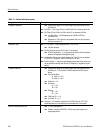
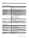
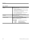
Table 1–1: Vertical deflection system
Category Description
Frequency Response REF: Specifications apply for full screen height video input signal with Vari-
able Gain off.
REQ: Flat Filter 1 V Full Scale: 50 kHz to 6 MHz within 2% of response at 50 kHz.
REQ: Flat Filter X5 Gain: 50 kHz to 6 MHz within 5% of response at 50 kHz.
REF: Low Pass Filter: w40 dB attenuation at 3.58 MHz (NTSC) or
4.43 MHz (PAL).
REF: Response at 15 kHz does not vary between Flat and Lum (low pass)
filters by more than 1%.
Deflection Factor REQ: 1 V Full Scale: 1 V input displayed within 1% of 140 IRE.
REF: Flat filter selected.
REQ: X5 Gain: Gain accuracy within 5% with 1 V input signal.
REF: X5 Gain Registration: v1 major division of vertical shift from baseline
between unmagnified and magnified signal.
REQ: Variable Gain Range: Input signals between 0.8 V and 2 V can be adjusted
to 140 IRE (1.0 V) display. 160 mV to 400 mV for X5 Gain.
REQ: Position Range: 1 V signal can be positioned so that peak white and sync tip
can be placed at blanking level with the DC Restorer on, regardless of gain
setting.
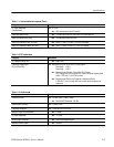
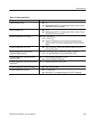
Transient Response REF: Specifications apply for full screen height video input signal with Vari-
able Gain off, 1 V Full Scale or X5 Gain selected, and Flat filter se-
lected.
REF: Pulse-to-Bar Ratio:
X1: 0.99:1 to 1.01:1.
X5: 0.98:1 to 1.02:1.
REF: Preshoot: v1%.
REF: Overshoot:
X1: v2%.
X5: v4%.
REF: Ringing:
X1: v2%.
X5: v4%.
REF: Field Rate Tilt: v1%.
REF: Line Rate Tilt: v1%.
REQ: Overscan: v2% variation in baseline of 100 IRE (700 mV) 12.5T (20T)
modulated pulse as it is positioned over the middle 80% of the screen.
Maximum Absolute Input Level REF: $5 VDC plus peak AC.
REF: Displays in excess of 200 IRE (1.428 V) may cause frequency re-
sponse aberrations.