


Adjustment Procedures
WFM 90 and WFM 91 Service Manual
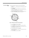
5–7
14. Select X5 GAIN from the Calibration menu, and then select X5 POS.
15. Adjust the Arrow Buttons to reposition the signal baseline back to the
graticule baseline.
16. Select X1 GAIN from the Calibration menu.
17. Select CAL MENU, and then select SAVE.
18. Remove the signal and terminator from the VIDEO IN connector.
Perform the following steps to adjust the frequency response:
1. Connect a 50 W precision cable from the output of the leveled sine wave
generator to the dual-input coupler using a 50 W-to-75 W minimum loss
attenuator.
2. Connect one side of the dual-input coupler to the VIDEO IN connector.
3. Connect the 015-0413-00 Peak-to-Peak Detector Head to the other end of the
dual-input coupler, using the female-to-female BNC connector.
4. Connect the other end of the Peak-to-Peak Detector Head to the 015-0408-00
Peak-to-Peak Detector + Input.
5. Connect the peak-to-peak detector Output to the digital multimeter, or an
oscilloscope.
6. Select EXT REF from the Configuration menu.
7. Set the leveled sine wave generator frequency to 50 kHz and adjust the
generator amplitude for exactly 100 IRE (700 mV PAL) of display.
8. Adjust the peak-to-peak detector Plus amplifier and input control until the
green LED is on.
9. Note the digital multimeter readout level or the oscilloscope dc level.
10. Set the sine wave generator frequency to 3.58 MHz (4.43 MHz PAL).
11. Adjust the amplitude of the sine wave generator so that the digital multime-
ter readout, or oscilloscope level, matches that noted in step 9.
12. Select X1 FREQ from the Calibration menu, and then select CAL.
13. Adjust the Arrow Buttons for a display amplitude of exactly 100 IRE
(700 mV PAL).
14. Select CAL MENU, and then select SAVE.
15. Select X5 GAIN from the Operating menu.
Frequency Response