


Troubleshooting Procedures
WFM 90 and WFM 91 Service Manual
6–41
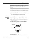
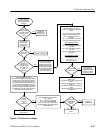
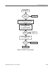
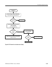
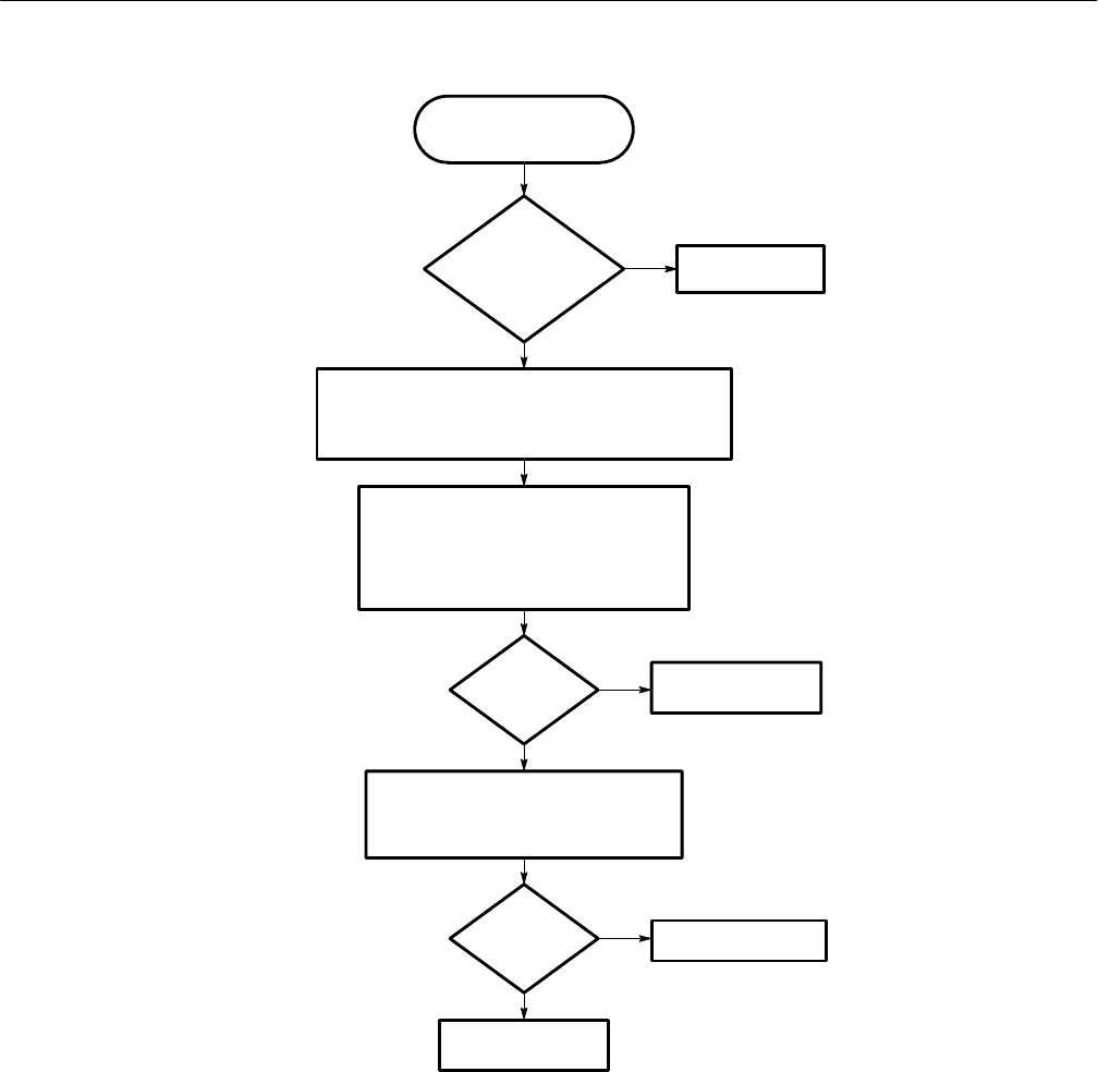
Replace the Top board.
Replace the
Bottom board.
Are the
Display drive
signals
ok?
Check the Display drive signals:
(Probe J16 from the back of the Bottom
board.)
J16-6 = (B) 2 VDC, 2.5 V peak video
J16-7 = (G) 2 VDC, 2.5 V peak video
J16-8 = (R) 2 VDC, 2.5 V peak video
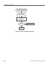
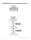
Is there a
display in any
other operating
mode (except
WIP)?
Check the SEL_EXVIDEO signal:
(Probe J16 from the back of the Bottom
board.)
J16-14 = +5 VDC in PIX mode
Is the
SEL_EXVIDEO
signal ok?
Replace the Display
module.
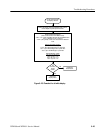
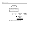
Use this procedure when
there is no display in the
Picture display mode.
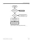
Go to Figure 6–17.
Remove the Display module and the Backlight board.
Power up the instrument. Connect a 100% flat field test
signal to the VIDEO INPUT. Select the Picture
display mode.
No
Yes
No
Yes
No
Yes
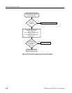
Figure 6–21: Flowchart for no picture display