


WFM 90 and WFM 91 Service Manual
3–1
Theory of Operation
This section contains a module-level description of the instrument circuitry.
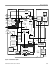
Block Diagram Description
The following description is based on the block diagram in Figure 3–1.
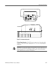
The signal input and output connectors are located on the Input board. There are
receivers for the three inputs, a switch for the video signal reference, and a
variable gain circuit for the audio input.
The video input signal has a DC voltage feedback clamp from the Bottom board.
The video output signal from the Bottom board is routed through the Input
board. The audio variable gain is controlled by the microprocessor serial bus,
which is routed to the Input board from the Top board through the Bottom board.
The Top board contains the microprocessor circuitry, the rasterizer and graphics
generator, the subcarrier oscillator, and the timing generator.
Microprocessor. The microprocessor takes input from the front-panel keypad to
control the operation of the instrument through the serial bus, parallel bus, and
dedicated control lines.
Rasterizer and Graphics. The rasterizer and graphics block produces all internally
generated video including waveforms, graticules, and menus. The rasterizer uses
the horizontal and vertical deflection signals to produce the waveforms. The
rasterizer uses the horizontal and vertical sync signals from the Bottom board to
lock to the incoming video signal.
The rasterizer needs a good analog timing voltage to run correctly. This timing
voltage is generated by a circuit loop between the Top and Bottom boards.
Problems with this circuit can be on either circuit board.
The Bottom board contains the power supply circuitry, the horizontal and
vertical deflection circuits, the NTSC or PAL decoder, the vectorscope and
burst-lock circuitry, the sync separator, and the audio amplifier for the headphone
output.
Input Board
Top Board
Bottom Board