


Troubleshooting Procedures
6–36
WFM 90 and WFM 91 Service Manual
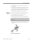
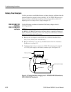
6. Connect a 75% color bar test signal to the VIDEO IN connector and connect
the VIDEO OUT connector to the picture monitor.
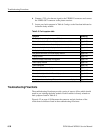
7. Locate your fault symptom in Table 6–5 and go to the flowchart indicated to
isolate the faulty module.
Table 6–5: Fault symptom table
Symptom Flowchart
No display after pressing the front panel ON button page 6–37
Graticule is ok, but the Waveform display is distorted or not visible page 6–38
Graticule is ok, but there is no Vector display page 6–39
Graticule is ok, but the Audio display is distorted or not visible page 6–40
No display in the Picture display mode page 6–41
Bad graticule and menu, but Picture display mode ok page 6–42
Display all white page 6–43
Waveform display mode sweep not triggered page 6–44
Vector display unlocked page 6–45
Vector display jitter page 6–46
Distorted vectors in Vector display page 6–46
Control problem page 6–47
Menus horizontally unlocked in Picture display mode page 6–48
Dim or blotchy display page 6–49
All display modes are bad except Picture, when no menus are displayed page 6–49
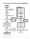
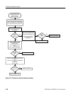
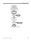
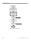
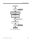
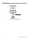
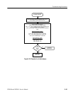
Troubleshooting Flowcharts
The troubleshooting flowcharts provide a series of steps to follow which should
result in you isolating the faulty module. Each flowchart is directly related to a
fault symptom listed in Table 6–5.
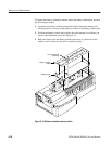
Figure 6–32 on page 6–50 illustrates the connector and pin locations of the
circuit board connectors listed in the troubleshooting flowcharts.