Acquiring Waveforms
3-16
CSA8000B & TDS8000B User Manual
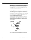
NOTE. Amplitude-related automatic measurements (for example, peak-to-peak
and RMS) will be accurate for vertical windows like those shown in
Figure 3 --2 a and b on page 3--15 because neither waveform is clipped (that is,
both waveforms are acquired). But if the signal amplitude were to extend outside
the vertical acquisition window, the data acquired becomes clipped. Clipped
data causes inaccurate results if used in amplitude-related automatic measure-
ments. Clipping also causes inaccurate amplitude values in waveforms that are
stored or exported for use in other programs.
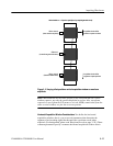
H The vertical position adjusts the display of the graticule relative to the
vertical acquisition window (position is a display control). Figure 3--2 b
shows how vertical position moves the waveform graticule vertically in the
vertical acquisition window to place the acquired waveform in the graticule
display. Position does not determine what data is acquired as does vertical
offset.
The vertical offset control affects the vertical acquisition window and the
displayed waveform as follows:
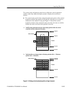
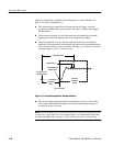
H The vertical range (window) is always centered around the offset value that
is set. Vertical offset is the voltage level at middle of the vertical acquisition
window. With no (zero) offset (see Figure 3--3), that voltage level is zero
(ground).
H As you vary vertical offset, the middle voltage level moves relative to zero.
This moves the vertical acquisition window up and down on the waveform.
With input signals that are smaller than the window, it appears the waveform
moves in the window. Actually, a larger signal shows what really happens:
the offset moves the middle of the vertical acquisition window up and down
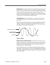
on input signal. Figure 3--3 shows how offset moves the acquisition window
to control the portion of the waveform amplitude the window captured.
H Applying a negative offset moves the vertical range down relative to the DC
level of the input signal, moving the waveform up on the display. Likewise,
applying a positive offset moves the vertical range up, moving the waveform
down on the display. See Figure 3--3.
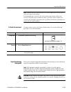
NOTE. On screen, the channel icon in the waveform bar points to the offset value
around w hich the vertical acquisition w indow is centered. The offset value
pointed to is relative to the ground reference icon. Both icons are shown in
Figure 3 --3.


