Acquiring Waveforms
CSA8000B & TDS8000B User Manual
3-5
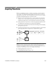
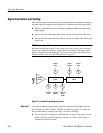
H Set horizontal scale to control the time duration of the horizontal acquisition
window to capture as much as you want of the input signal(s). To control
where in the input signal (data stream) that the horizontal acquisition
window acquires, you set horizontal position to delay the window relative to
a trigger to capture the waveform portion you want. To increase or decrease
the resolution between sample points, change the record length.
For more background on the acquisition window concepts, s ee Signal Condition-
ing Background on page 3--13.
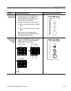
A Versatile Autoset. Autoset can be defined to set up for a waveform edge, period,
or an eye/bit pattern. Pushing the Autoset button automatically sets up the
instrument controls for a usable display based on the property you choose and
the characteristics of the input signal. Autoset is much faster and easier than a
manual control-by-control setup. You can also reset the instrument to its factory
default settings by pushing the Default Setup button.
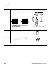
The vertical offset cannot be adjusted for any reference waveform, because a
reference waveform is a static, saved waveform, and offset adjusts the acquisi-
tion hardware for acquiring live waveforms. Also, TDR waveforms, if displayed
in rho or ohm units, cannot be adjusted for vertical offset.
The vertical offset of a math waveform cannot be adjusted directly. You can
adjust the of fset of waveform sources (waveforms included in the math
expression) for the math waveform if the sources are live waveforms.
The key points that follow describe operating considerations for setting up input
scaling, offset, and position to properly acquire your waveforms.
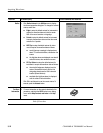
Sampling Modules Selection and Signal Connection. Select the sampling module,
optical or electrical, that best fits your sampling task, whether it is connecting to
a fiber or electrical cable to test a digital data stream, or to a test fixture through
SMA cables to characterize a device. The connection to the sampling module
depends on your application.
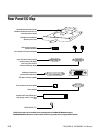
Tektronix provides 80E00-series (electrical) and 80C00-series (optical) sampling
modules for this instrument; you can read about any sampling module and its
connections in the sampling-module user manual(s) that shipped with your
product. (Insert your sampling-module user manual(s) in Appendix C at the back
of this manual for ready reference.) You can also check your Tektronix catalog
for connection accessories that may support your application.
Up to eight acquisition channels are available, depending on the sampling
modules installed. Each channel can be displayed as a waveform or can
contribute waveform data to other waveforms (math and reference waveforms,
for example).
What’s Special?
What’s Excluded?
Keys to Using


