Incoming Inspection
CSA8000B & TDS8000B User Manual
1-29
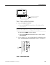
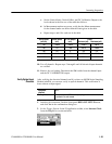
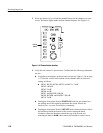
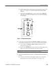
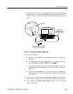
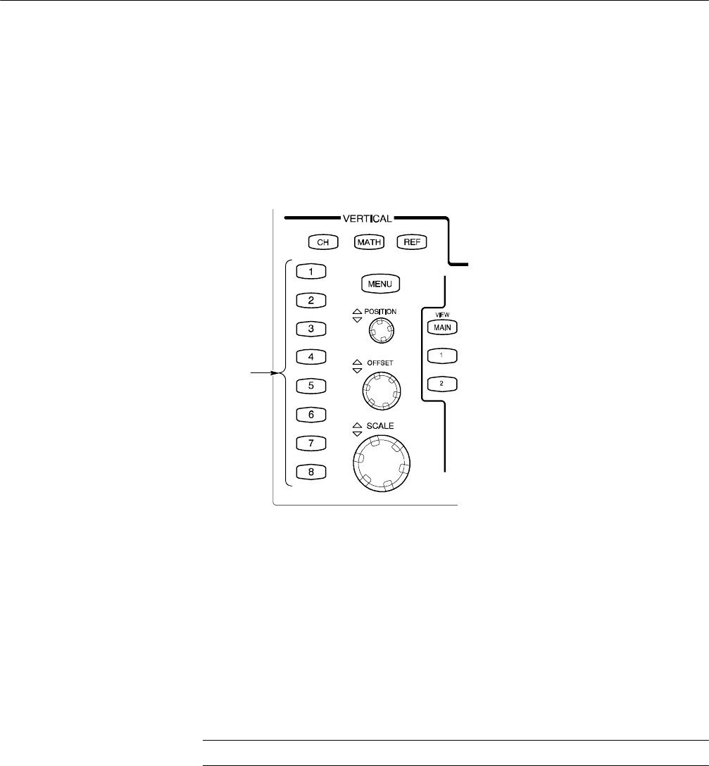
d. Push the channel button for the channel you connected to in step 2. See
Figure 1--12 on page 1--29. The button lights and the channel display
comes on.
e. T urn the Vertical SCALE knob to set the vertical scale to 20 mV/div.
The channel scale readout is displayed in the Control bar at the bottom
of the graticule.
Channel
buttons
Figure 1- 12: Channel button location
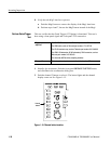
4. Set the time base: Set the Horizontal SCALE to 1 s/div. The horizontal
scale readout is displayed in the Control bar at the bottom of the graticule.
a. Set the display for Normal and Show Vectors (enable). See To Set
Display Styles on page 3--68.
b. Rotate vertical OFFSET knob counterclockwise so that the base of the
square wave is about 2 divisions below the center graticule.
NOTE. Otherwise, no vertical trace will be seen for rise and fall.
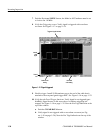
5. Verify that the Main time base operates: Confirm the following statements
are true:
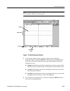
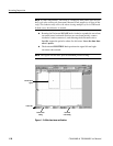
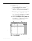
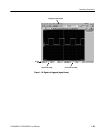
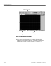
H One period of the internal clock signal (a square wave) is about five
horizontal divisions on-screen. See Figure 1--13 on page 1--30.


