Table of Contents
CSA8000B & TDS8000B User Manual
vii
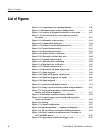
Figure 3--12: Triggered versus untriggered displays 3--41.............
Figure 3--13: Trigger inputs 3--42.................................
Figure 3--14: Holdoff adjustment can prevent false triggers 3--46.......
Figure 3--15: Trigger to En d Of Record Time (EORT) 3--47...........
Figure 3--16: Display elements 3--54...............................
Figure 3--17: Horizontal position includes time to Horizontal
Reference 3--59.............................................
Figure 3--18: Graticule, cursor and automatic measurements 3--73.....
Figure 3--19: Measurement an notations on a waveform 3--75..........
Figure 3--20: High/Low tracking methods 3--78......................
Figure 3--21: Reference-level calculation methods 3--79...............
Figure 3--22: Horizontal cursors measure amplitudes 3--86............
Figure 3--23: Components determining Time cursor readout
values 3--88................................................
Figure 3--24: Functional transformation of an acquired
waveform 3--101.............................................
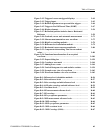
Figure 3--25: Export dialog box 3--129..............................
Figure 3--26: Creating a user mask 3--144...........................
Figure 3--27: Adding a new vertex 3--144............................
Figure 3--28: Vertical histogram view and statistics on data 3--154.......
Figure 3--29: Normal vector view of a waveform 3--163................
Figure 3--30: Waveform database view of a waveform 3--163............
Figure B--1: Reference-level calculation methods B--56................
Figure B--2: Pulse-reference levels B--57............................
Figure B--3: Pulse crossings and mid-reference level B-- 58.............
Figure B--4: AOP pulse crossings and mid-reference level B--59........
Figure B--5: Overshoot levels B--59................................
Figure B--6: RZ measurement reference levels B--60..................
Figure B--7: RZ crossings B--61...................................
Figure B--8: RZ eye--aperture parameters B--62......................
Figure B--9: NRZ measurement refer ence levels B--63.................
Figure B--10: NRZ crossings B--64.................................
Figure B--11: NRZ eye-aperture parameters B--65....................
Figure B--12: NRZ overshoot levels B--66...........................
Figure B--13: NRZ Crossings (OMA) B--67..........................


